 Products Home / Technical Resources / Polarization Optics Technical Publications / Choosing a Wave Plate
Choosing a Wave Plate

Please Wait

Choosing a Wave Plate
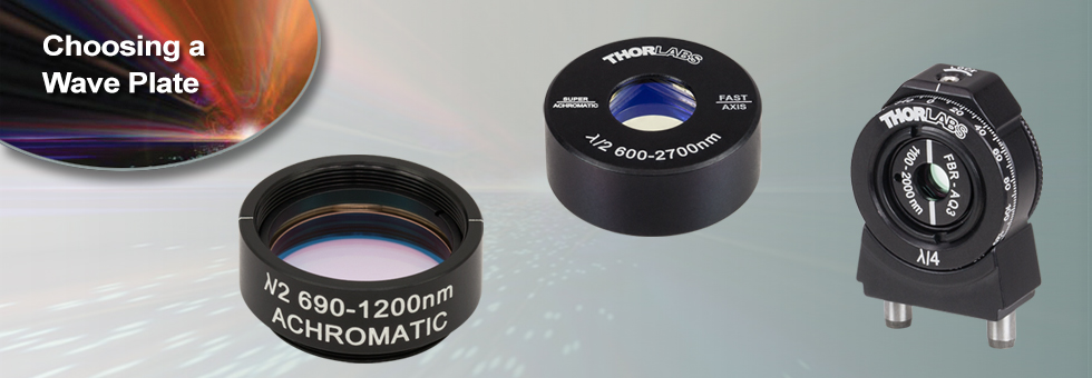
Thorlabs offers achromatic, superachromatic, zero-order (both unmounted wave plates and mounted wave plates), low-order, and multi-order wave plates (single wavelength and dual wavelength) with either λ/4 or λ/2 phase shift.
Achromatic Wave Plates provide phase retardance that is relatively independent of wavelength over a wide spectral range, and Superachromatic Wave Plates provide phase retardance almost entirely independent of wavelength over a much wider range than achromatic wave plates. In contrast, zero-order and multi-order wave plates provide a phase shift that is strongly wavelength dependent. Our achromatic wave plates are available with four operating ranges: 260 - 410 nm, 400 - 800 nm, 690 - 1200 nm, and 1100 - 2000 nm. Additionally, we offer superachromatic wave plates for the 310 - 1100 nm and 600 - 2700 nm ranges.
| Round Zero-Order Wave Plate Comparison | ||
|---|---|---|
| Material | Quartz | LCP |
| Sizes | Ø1/2" and Ø1" | Ø1" and Ø2" |
| Mounted Versions Available | Yes | Yes |
| Retardances Available | 1/4 λ and 1/2 λ | 1/4 λ and 1/2 λ |
| Retardance Accuracy | <λ/300 | <λ/100 |
| Surface Quality | 20-10 Scratch-Dig | 60-40 Scratch-Dig |
| Coating | V Coat | Broadband AR |
| Coating Reflectance (per Surface) |
0.25% | 0.5% Average Over Specified Coating Range |
Zero-order wave plates are designed such that the phase shift created is exactly one quarter or one half of a wave. They offer substantially lower dependence on temperature and wavelength than multi-order wave plates. Our Zero-Order Quartz Half-Wave and Quarter-Wave Plates are composed of two wave plates stacked together with the fast axis of one aligned to the slow axis of the other to achieve zero-order performance. Thorlabs' zero-order wave plates are available for a number of discrete wavelengths ranging from 266 nm to 2020 nm. Our Polymer Zero-Order Half-Wave and Quarter-Wave Plates consist of a thin layer of liquid crystal polymer retarding material sandwiched between two glass plates and are available at discrete wavelengths between 405 nm and 1550 nm. Our quartz zero-order wave plates provide better retardance accuracy and lower reflectance (see table), while our LCP zero-order wave plates produce a smaller decrease in retardance at larger AOIs. In addition, Thorlabs also offers unmounted true Zero-Order Telecom Wave Plates for WDM applications.
MIR Wave Plates are made from a single piece of high-quality magnesium fluoride and provide either quarter-wave or half-wave retardance at 2.5 µm, 3.5 µm, 4.0 µm, 4.5 µm, or 5.3 µm. Light passing through these MIR wave plates will undergo a low number of full or partial wavelength shifts (also referred to as the order, or m) in addition to the fractional design retardance. This differs from true zero-order and multi-order wave plates which undergo no shift or a high number of shifts, respectively. The low-order design maintains near to true zero-order performance, making it a good alternative to true zero-order wave plates. The single magnesium fluoride substrate is also thinner compared to a zero-order design, which combines two multi-order wave plates, making our low-order retarders well suited for applications that are sensitive to dispersion.
Multi-Order Wave Plates are made such that the retardance of a light path will undergo a certain number of full wavelength shifts (also referred to as the order, or m) in addition to the fractional design retardance. Compared to their zero-order counterparts, the retardance of multi-order wave plates is more sensitive to wavelength and temperature changes. Multi-order wave plates are, however, a more economical solution for many applications where increased sensitivities are not an issue. Our multi-order wave plates are available for a number of discrete wavelengths ranging from 266 nm to 1550 nm. Thorlabs also offers Dual-Wavelength Multi-Order Wave Plates designed for use at both 532 nm and 1064 nm.
In addition to these options, Thorlabs also has the ability to design and manufacture custom wave plates for both OEM sales and individual low quantity orders. Our technical staff is able to help with all phases of your request: quoting, sales, and planning and manufacturing support. If you have a custom request or a question about our capabilities, please contact Tech Support to start a discussion.
Operating Principle of Wave Plates
Optical wave plates are constructed from birefringent materials that have a difference in refractive index between two orthogonal axes. This birefringent property introduces a velocity difference between light polarized along the fast and slow principal axes of the wave plate. The fast principal axis of the wave plate has a lower refractive index, resulting in a faster velocity for light polarized in this direction. Conversely, the slow axis has a higher refractive index, resulting in a slower velocity for light with this polarization. When light passes through a wave plate, this velocity difference leads to a phase difference between the two orthogonal polarization components. The actual phase shift depends on the properties of the material, the thickness of the wave plate, and the wavelength of the signal, and can be described as:
![]()
where n1 is the refractive index along the slow axis, n2 is the refractive index along the orthogonal fast axis, d is the thickness of the wave plate, and λ is the signal wavelength.
Using a Wave Plate
Wave plates are typically available with a retardance of λ/4 or λ/2, meaning that a phase shift of a quarter wavelength or a half a wavelength (respectively) is created.
Half-Wave
As described above, a wave plate has two principal axes: fast and slow. Each axis has a different refractive index and, therefore, a different wave velocity. When a linearly polarized beam is incident on a half-wave plate, and the polarization of this beam does not coincide with one of these axes, the output polarization will be linear and rotated with respect to the polarization of the input beam (see image at right). When applying a circularly polarized beam, a clockwise (counterclockwise) circular polarization will transform into a counterclockwise (clockwise) circular polarization.
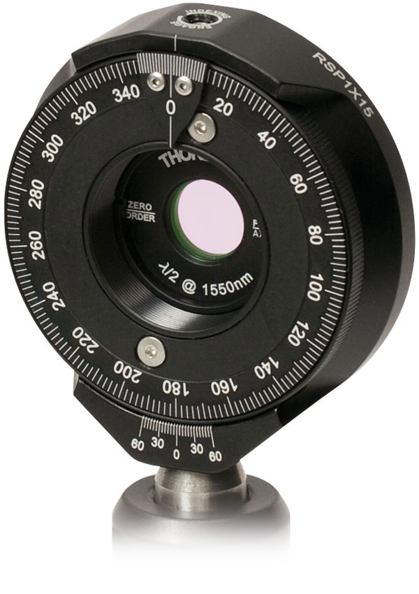
Half-wave (λ/2) plates are typically used as polarization rotators. Mounted on a rotation mount, a λ/2 wave plate can be used as a continuously adjustable polarization rotator, as shown below. Additionally, when used in conjunction with a Polarizing Beamsplitter a λ/2 wave plate can be used as a variable ratio beamsplitter.
The angle between the output polarization and the input polarization will be twice the angle between the input polarization and the wave plate’s axis (see diagram to the lower right). When the polarization of the input beam is directed along one of the axes of the wave plate, the polarization direction will remain unchanged.
Quarter-Wave
A quarter-wave plate is designed such that the phase shift created between the fast and slow axes is a quarter wavelength (λ/4). If the input beam is linearly polarized with the polarization plane aligned at 45° to the wave plate's fast or slow axis, then the output beam will be circularly polarized (see image at right). If the linearly polarized beam is aligned at an angle other than 45°, then the output will be elliptically polarized. Conversely, the application of a circularly polarized beam to a λ/4 wave plate results in a linearly polarized output beam. Quarter wave plates are used in Optical Isolators, optical pumps, and EO Modulators.
| Posted Comments: | |
| No Comments Posted |