 Products Home / Technical Resources / Optical Elements Technical Publications / Bandpass Filter Tutorial
Bandpass Filter Tutorial

Please Wait

Click to Enlarge
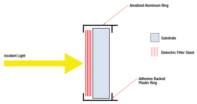
The number of layers shown in this schematic is not indicative of the number of layers in an actual bandpass filter. The drawing is also not to scale.
Hard-Coated Bandpass Filter Structure
A bandpass filter is created by depositing layers of material on the surface of the substrate. For our hard-coated bandpass filters, the coating is comprised of dielectric stacks alternating with dielectric spacer layers. Each dielectric stack is composed of a large number of alternating layers of low-index and high-index material. The thickness of each layer in the dielectric stack is λ/4, where λ is the central wavelength of the bandpass filter (i.e. the wavelength with the highest transmittance through the filter). The spacer layers are placed in between the stacks and have a thickness of (nλ)/2, where n is an integer. A Fabry-Perot cavity is formed by each spacer layer sandwiched between dielectric stacks. The filter is mounted in an engraved metal ring for protection and ease of handling.
Filter Operation Overview
The constructive interference conditions of a Fabry-Perot cavity allow light at the central wavelength, and a small band of wavelengths to either side, to be transmitted efficiently, while destructive interference prevents the light outside the passband from being transmitted. However, the band of blocked wavelengths on either side of the central wavelength is small. To increase the blocking range of the filter, materials with broad blocking ranges are used as the substrate or to coat the spacer layers. Although these materials effectively block out-of-band transmission of incident radiation, they also decrease the transmission through the filter in the passband.
Filter Orientation
An engraved arrow on the edge of the filter is used to indicate the recommended direction for the transmission of light through the filter. Orienting the coated side toward the source will reduce unwanted scattering and minimize reflections sent back toward the source. Using the filter in the opposite orientation will not, however, significantly affect the performance of the filter. The plot to the bottom left was made by illuminating the filter with a low intensity broadband light and measuring the transmission as a function of wavelength. The plot shows that the direction of transmission through the filter has very little effect on the intensity and the spectrum of the light transmitted through the filter. The minimal variation between the forward and backward traces is most likely due to a small shift in the incident angle of the light on the filter introduced when the filter was removed, flipped over, and replaced in the jig.
The filter is intended to be used with collimated light normally incident on the surface of the filter. For uncollimated light or light striking the surface at an angle not normally incident to the surface, the central wavelength (wavelength corresponding to peak transmission) will shift toward lower wavelengths and the shape of the transmission region (passband) will change. Varying the angle of incidence (AOI) by a small amount can be used to effectively tune the passband over a narrow range. Large changes in the incident angle will cause larger shifts in the central wavelength but will also significantly distort the shape of the passband and, more importantly, cause a significant decrease in the transmittance of the passband, as seen in the plot to the bottom right.
Filter Temperature
The central wavelength of the filter can be tuned slightly (~1 nm over the operating range of the filter) by changing the temperature of the filter. This is primarily due to the slight thermal expansion or contraction of the layers.
Click to Enlarge
This plot displays transmission forward (solid lines) and backward (dashed lines) through the FBH800-10 Premium Bandpass Filter and the FBH800-40 Premium Bandpass Filter. The nearly perfect overlap of the solid and dashed lines shows that the direction of transmission through the filter has little effect on the intensity and spectrum of light transmitted through the filter.
Click to Enlarge
This plot displays transmission through the FBH800-10 Premium Bandpass Filter at varying angles of incidence (AOI).
| Posted Comments: | |
Freddy Narea
(posted 2020-01-24 14:21:03.893) Hi. These filters can be used as tunable filters (interference filters).
If so, do you have a filter that allows tuning from the visible to the infrared? YLohia
(posted 2020-01-24 03:07:26.0) Hello, thank you for contacting Thorlabs. What specific wavelength range are you looking to target? I have reached out to you directly to discuss this further. |