 Products Home / Technical Resources / Optical Elements Technical Publications / Spatial Filters Tutorial
Spatial Filters Tutorial

Please Wait
Principles of Spatial Filters
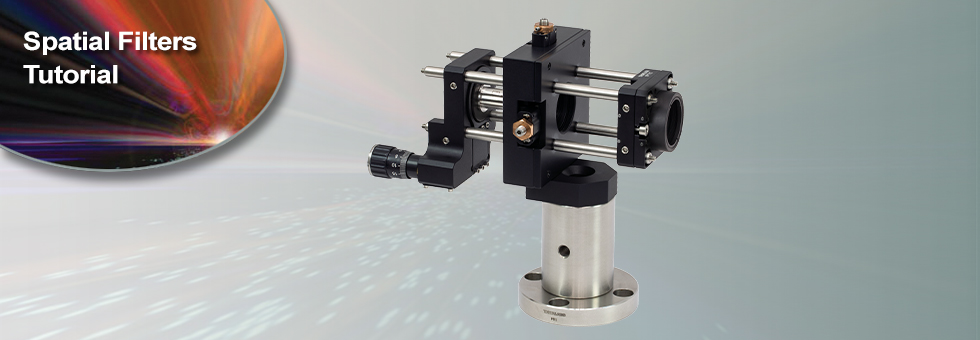
For many applications, such as holography, spatial intensity variations in the laser beam are unacceptable. Our KT311(/M) spatial filter systems are ideal for producing clean Gaussian beams.
Figure 1: Spatial Filter System
The input Gaussian beam has spatially varying intensity "noise". When a beam is focused by an aspheric lens, the input beam is transformed into a central Gaussian spot (on the optical axis) and side fringes, which represent the unwanted "noise" (see Figure 2 below). The radial position of the side fringes is proportional to the spatial frequency of the "noise".
Figure 2
By centering a pinhole on a central Gaussian spot, the "clean" portion of the beam can pass while the "noise" fringes are blocked (see Figure 3 below).
Figure 3
The diffraction-limited spot size at the 99% contour is given by:

where λ = wavelength, ƒ=focal length and r = input beam radius at the 1/e2 point.
Choosing the Correct Optics and Pinhole for Your Spatial Filter System
The correct optics and pinhole for your application depend on the input wavelength, source beam diameter, and desired exit beam diameter.
For example, suppose that you are using a 650 nm diode laser source that has a diameter (1/e2) of 1.2 mm and want your beam exiting the spatial filter system to be about 4.4 mm in diameter. Based on these parameters, the C560TME-B mounted aspheric lens would be an appropriate choice for the input side of spatial filter system because it is designed for use at 650 nm, and its clear aperture measures 5.1 mm, which is large enough to accommodate the entire diameter of the laser source.
The equation for diffraction limited spot size at the 99% contour is given above, and for this example, λ = (650 x 10-9 m), f = 13.86 mm for the C560TM-B, and r = 0.6 mm. Substitution yields
Diffraction-Limited Spot Size (650 nm source, Ø1.2 mm beam)
The pinhole should be chosen so that it is approximately 30% larger than D. If the pinhole is too small, the beam will be clipped, but if it is too large, more than the TEM00 mode will get through the pinhole. Therefore, for this example, the pinhole should ideally be 19.5 microns. Hence, we would recommend the mounted pinhole P20K, which has a pinhole size of 20 μm. Parameters that can be changed to alter the beam waist diameter, and thus the pinhole size required, include changing the input beam diameter and focal length of focusing lens. Decreasing the input beam diameter will increase the beam waist diameter. Using a longer focal length focusing lens will also increase the beam waist diameter.
Finally, we need to choose the optic on the output side of the spatial filter so that the collimated beam's diameter is the desired 4.4 mm. To determine the correct focal length for the lens, consider the following diagram in Figure 4, which is not drawn to scale. From the triangle on the left-hand side, the angle is determined to be approximately 2.48o. Using this same angle for the triangle on the right-hand side, the focal length for the plano-convex lens should be approximately 50 mm.
Figure 4: Beam Expansion Example
For this focal length, we recommend the LA1131-B plano-convex lens [with f = 50 mm at the design wavelength (λ = 633 nm), this is still a good approximation for f at the source wavelength (λ = 650 nm)].
Note: The beam expansion equals the focal length of the output side divided by the focal length of the input side.
For optimal performance, a large-diameter aspheric lens can be used in place of a plano-convex lens if the necessary focal length on the output side is 20 mm (see AL2520-A, AL2520-B, AL2520-C). These lenses are 25 mm in diameter and can be held in place using the supplied SM1RR Retaining Ring.
| Posted Comments: | |
| No Comments Posted |