 Products Home / Technical Resources / Fiber Components Technical Publications / Using the Fiber Polarization Controller Lab Facts
Using the Fiber Polarization Controller Lab Facts

Please Wait

Click to Enlarge
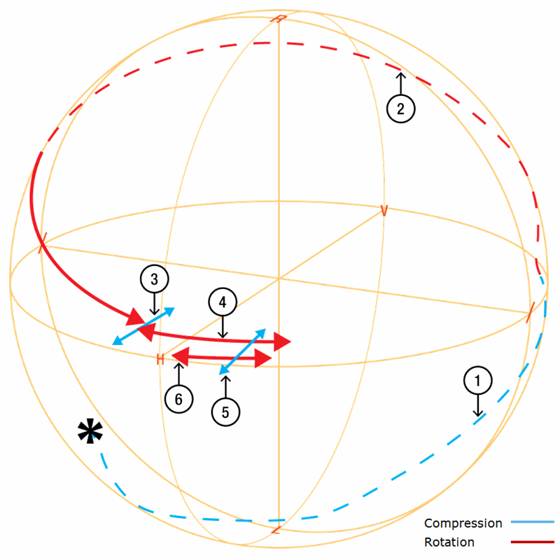
Figure 2: Poincaré sphere showing the polarization rotation from a PLC-900.

Click to Enlarge
Figure 1: Forces produced by the PLC-900.
Thorlabs Lab Fact: Using the Fiber Polarization Controller to Manipulate Polarization
We present laboratory measurements of the influence on the output polarization state from a fiber due to rotational and compression forces from the in-line fiber optic polarization controller. This test was done using the legacy PLC-900 polarization controller; our CPC900 and CPC250 polarization controllers perform in the same way as the PLC-900. The controllers utilize the effects of stress-induced birefringence to create changes in the polarization of light traveling through a fiber under stress. The stress can be caused either through compression [1] or rotation [2], as shown in Figure 1. It was found that the stress-induced birefringence can be adjusted continuously, thus allowing any arbitrary input polarization state to be rotated into any desired output polarization state. We detail the procedures necessary to achieve a desired output polarization, and plot the change in the polarization on a Poincaré sphere to illustrate the steps necessary in reaching a desired polarization state.
For our experiment, we used the S1FC1310 Fabry-Perot Benchtop Laser (1310 nm) as the light source and couple it into a Ø900 µm tight-buffer fiber. The fiber is mounted through the PLC-900, and the output was collimated into a free-space beam with a fiber collimator. From here the beam was measured, either directly by a polarimeter or through an analyzer assembly consisting of a λ/4 wave plate, a linear polarizer, and a power meter.

Figure 2 summarizes the measured results for manipulating the polarization of light in a fiber as a function of rotational and compression forces and is shown on the Poincaré sphere. The blue lines represent compression and the red lines represent rotation of the PLC-900 (see Fig. 1); the numbers indicate the step. As shown in Fig. 2, starting at any arbitrary polarization state, it is possible to achieve any desired polarization state through a series of rotations and compressions. This manipulation of the polarization by the PLC-900 does not produce intrinsic loss nor back reflections; instead stress-induced birefringence is utilized as a mechanism for rotating the polarization of light in fiber. Data is presented for both compression and rotation forces, and the polarization changes due to these are mapped out on Poincaré spheres. For details on the experimental setup employed and the results obtained, please click here.
[1] A.M. Smith, “Single-mode fibre pressure sensitivity,” Electron Lett. 16, 773-774 (1980).
[2] R. Ulrich, A. Simon, “Polarization optics of twisted single-mode fibers” Appl Opt 18, 2241-2251 (1979).
| Posted Comments: | |
| No Comments Posted |