 Products Home / Actuators, Adjusters, & Transducers / Piezoelectric Chips and Stacks / Vibrating Piezoelectric Actuator
Vibrating Piezoelectric Actuator

- Single Layer of Soft PZT Material with Electrodes and Alumina End Plates
- High Frequency Scanning up to 1.5 MHz
- 160 nm Free Stroke Displacement
- Low-Voltage Piezo Stack with 200 V Max Voltage
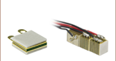
PA5FBP3
Vibrating Piezo Actuator,
Arrow Indicates Direction of Expansion


Please Wait
| Piezo Selection Guide |
|---|
| Piezoelectric Ceramic Chips |
| Square |
| Square with Through Hole |
| Round |
| Ring |
| Tube |
| Shear |
| Benders |
| Single-Crystal Piezoelectric Chips |
| Square |
| Piezoelectric Ceramic Stacks |
| Discrete, Square |
| Discrete, Square with Through Hole |
| Discrete, Round |
| Discrete, Ring |
| Discrete, Hermetically Sealed |
| Discrete, Shear (1D to 3D Positioners) |
| Co-Fired: Square, Square with Through Hole, Round, & Ring |
| Co-Fired or Discrete: Square with Strain Gauges |
| Piezoelectric Crystal Stacks |
| Square |
| Mounted Piezoelectric Actuators |
| Ultrasonic Piezo Chips & Transducers |
| Vibrating Piezo Actuator |
| Webpage Features | |
|---|---|
| Clicking this icon below will open a window that contains specifications, mechanical drawings, and graphs. | |
Features
- Maximum Drive Voltage Range of 0 - 200 V
- 160 nm Free Stroke Displacement
- Convenient Package With Alumina End Plates and Copper Leads
- Ideal for Atomic Force Microscopes (AFMs) and Ultrasonic Vibrations
The PA5FBP3 Vibrating Piezo Actuator consists of a soft Lead Zirconate Titanate (PZT) material sandwiched between copper foils, with leads extending out from the part for easy access for soldering. The positive electrode is indicated by the longer copper lead. Alumina end plates complete the actuator stack, providing a nonconductive, flat surface for convenient mounting and safe handling.
The PA5FBP3 actuator is designed for high frequency vibration applications such as AFMs. In tapping mode, an AFM has a piezo-driven cantilever oscillating near the surface of the part under test, instead of a probe in constant contact with the part. This allows soft materials to be measured without the probe affecting the measurement or damaging the surface of the material. The PA5FBP3 actuator is well suited for this application with the capability of oscillating a cantilever at 100s of kHz with displacements on the order of 100 nm.
Soft PZT material has a large piezoelectric constant and is ideal for actuators in motion control applications. This material also has a relatively high dielectric loss factor of ~2% and generates excessive heat when driven near resonance. We recommend using soft PZT actuators at less than 33% of their resonant frequency to avoid overheating the device. The maximum drive frequency, while operating within the recommended operating temperature range, will depend on the specific application. For AFM applications, with drive voltages in the range of 0 V - 10 V, no external cooling is required for vibrations on the order of 100s of kHz . Please see the Operation tab for more information on device operation.
Piezo chips with custom dimensions, voltage ranges, and coatings are available. Additionally, customers can order these piezo chips in high-volume quantities. Please contact OEM Sales for more information.
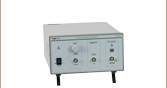
Piezo Driver
We recommend Thorlabs' HVA200 High-Voltage Amplifier to drive the PA5FBP3 actuator. The amplifier provides a maximum output voltage of ±200 V, a continuous current output of up to 100 mA, and a 1 MHz bandwidth, with a low output noise of 1.5 mV (RMS). An adjustable bias allows for precise DC offset control to provide the 0 V to +200 V output range needed for this piezo actuator.
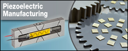
Thorlabs' In-House Piezoelectric Manufacturing
Our piezoelectric chips are fabricated in our production facility in China, giving us full control over each step of the manufacturing process. This allows us to economically produce high-quality products, including custom and OEM devices. A glimpse into the fabrication of our piezoelectric chips follows. For more information about our manufacturing process and capabilities, please see our Piezoelectric Capabilities page.
- Build Blocks from Lead Zirconate Titanate (PZT) or BiScO3-PbTiO3 (BSPT) Powder
- Dry Press PZT or BSPT Powder into Square Elements with Binder in a Mold
- Purge Solvent and Binder Material Residues by Heat Treating the Elements
- Sinter the Elements to Fuse the Piezoelectric Pressed Powder and Grow PZT or BSPT Crystals
- Lap the Elements to Achieve Tight Dimensional Tolerances: ±0.1 mm for Each Element
- Screen Print the Outer Electrodes on the Elements
- Align the Individual PZT or BSPT Crystals Along the Same Axis by Poling the Elements
Operation Notes
Electrical Considerations
Electrical connection to the external electrodes can be achieved by mechanical contacts, soldering, gluing with electrically conductive glues, or wire bonding. The copper foil with a longer lead should be connected to the positive electrode. The maximum drive voltage is 200 V. Exceeding 200 V will decrease the lifespan of the device and may cause mechanical failure. Reverse biasing the device may also cause mechanical failure.
Click to Enlarge
The temperature rise was measured after applying a sine-wave driving voltage, 0 V to 200 V, at the specified frequency for 10 min, at room temperature without cooling. With lower maximum voltage or extra cooling measures, the working frequency can be higher, but the temperature of the device should be kept <130 °C (266 °F).
Caution: After driving, the piezo is fully charged. Directly connecting the positive and negative electrodes has the risk of electricity discharging, spark, and even failure. We recommend using a resistor (>1 kΩ) between the electrodes to release the charge.
Soldering Wire Leads to the Electrodes
When soldering wires to the copper foil leads, use a temperature no greater than 370 °C (700 °F) for a maximum of 2 seconds per spot. Solder the lead to the middle of the electrode (where the through hole is) and keep the region over which heat is applied as small as possible.
Operating Under High-Frequency Dynamic Conditions
It may be necessary to implement an external temperature-control system to cool the device when it is operated at high frequencies. High-frequency operation causes the internal temperature of the piezoelectric device to rise. The dependence of the device temperature on the drive voltage frequency for a 0 V - 200 V sine-wave driving voltage with no external cooling is shown at the right. Lower voltage ranges or external cooling will allow the device to be operated at higher frequencies. The maximum operating frequency will depend on the specific application and external cooling measures. The temperature of the device should not exceed the maximum operating temperature of 130 °C (266 °F).
Attaching Devices to the Piezo
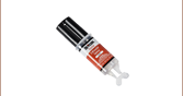
Any epoxy which cures at a temperature lower than 80 °C (176 °F) is safe to use with these PZT piezos. We recommend Thorlabs Item #'s 353NDPK or TS10. Loctite Hysol 9340 is also usable. Loads should only be attached to the central area of the largest face. Attaching a load to the smaller faces may lead to mechanical failure.
Storage Instructions
- Do not store the device at temperatures above 80 °C.
- Do not store the device in humid environments. The relative humidity (RH) should be less than 40%.
- Do not immerse the device in organic solvents.
- Do not use the device around combustible gases or liquids.
| Posted Comments: | |
user
(posted 2023-02-15 13:59:08.92) Can I know the datasheet about vibrating frequency according to voltage? cdolbashian
(posted 2023-04-03 02:08:55.0) Thanks for contacting Thorlabs. There is no datasheet about vibrating frequency vs voltage. The piezo is supposed to operate with no higher than 1/3 of resonant frequency. Lower voltage ranges or external cooling will allow the device to be operated at higher frequencies. The maximum operating frequency will depend on the specific application and external cooling measures. |
| Item #a | Infob | Displacementc (Free Stroke) |
Resonant Frequencyd |
Drive Voltage Range | Capacitancee | Outer Dimensions |
End Faces |
|---|---|---|---|---|---|---|---|
| PA5FBP3 | 160 nm ± 20% | 4.5 MHz | 0 - 200 V | 1.6 nF ± 15% | 5.0 mm x 8.0 mm x 1.8 mm | Alumina End Plates, Copper Leads |
- All specifications are quoted at 25 °C, unless otherwise stated.
- Click on the blue icon
 for specifications, drawing, performance plots, and downloadable data.
 - The "free stroke" displacement corresponds to no load at 200 V.
- Under No Load
- Specified at 1 kHz, 1 VRMS