Products Home / Fiber Components / Fused Fiber Optic Couplers / Splitters / 1x2 SM Fiber Couplers/Taps / 405 nm Single Mode Fused Fiber Optic Couplers / Taps
405 nm Single Mode Fused Fiber Optic Couplers / Taps
- Narrowband Couplers for Use at 405 nm
- Available in Any Split Ratio Starting from 99:1
- Unterminated Fibers, FC/PC Connectors, or FC/APC Connectors
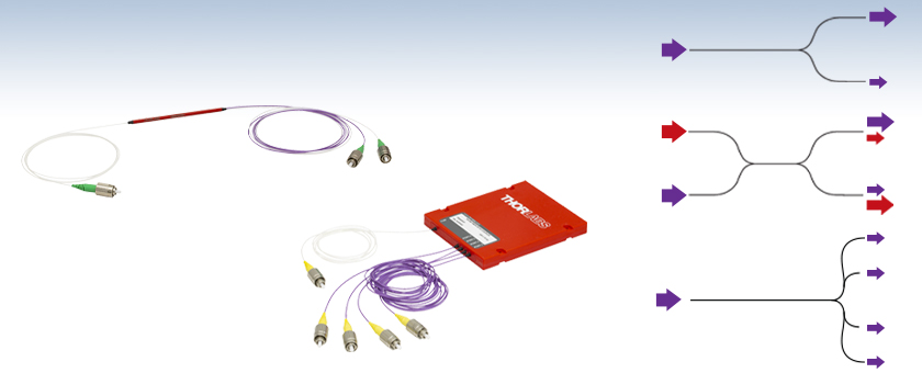
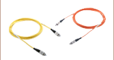
405 nm 1x2 Narrowband Coupler
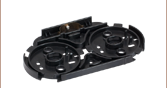
405 nm 1x4 Narrowband Coupler
1x2
2x2
1x4


Please Wait
Contact tech support to discuss your 405 nm application with one of our specialists.
Click for Details
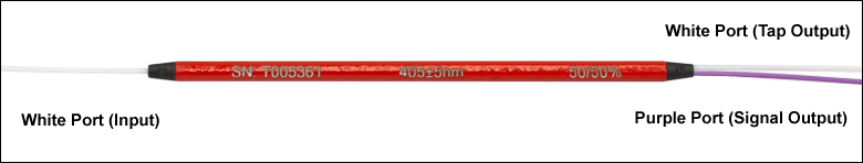
Example image of a 1x2 coupler. The coupling ratio corresponds to the ratio of the measured output power from the white (signal output) port to the purple (tap output) port.
Features
- Contact Us for Single Mode Fused Fiber Optic Couplers for Use at 405 nm
- Wavelength Range: 405 ± 5 nm
- 1x2, 2x2, or 1x4 Configurations Available
- Any Split Ratio Starting from 99:1 Available
- Unterminated Fibers, FC/PC Connectors, or FC/APC Connectors
Thorlabs offers narrowband couplers for 405 ± 5 nm that can be made with any split ratio starting from 99:1. They are offered in 1x2, 2x2, or 1x4 configurations. Due to the short wavelength of 405 nm light, there are additional factors that must be considered when deciding the type of 405 nm coupler that is appropriate for a given application (see the Key Considerations section below). More general information on the operation of 1x2, 2x2, or 1x4 couplers is provided on the Coupler Tutorial tabs. If you are interested in a 405 nm fiber coupler, please contact tech support to discuss your needs with one of our specialists.
Click to Enlarge
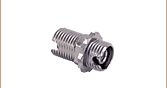
Pure Silica Core Fiber
Key Considerations
Fibers
Two different optical fiber designs offer single mode propagation at 405 nm: germanium (Ge) doped and pure silica core fibers. They both typically have an operating wavelength range of 400 to ≥635 nm. For an NA of 0.12, a germanium-doped fiber will have a core of Ø2.1 µm. For the same NA, the pure silica core fiber will have a core of Ø3.0 µm.
Core Size
The core diameter necessary for single mode operation at 405 nm is more than three times smaller than for a 1550 nm fiber such as Corning SMF-28. Due to their very small core sizes, these fibers need to be centered to extremely tight tolerances when terminated with FC/PC or FC/APC optical connector ferrules. When connectors are mated together, such as in a bulkhead, any misalignment of the fiber cores can create significant optical losses. Furthermore, splicing of small core SM optical fibers requires specialized equipment for optimal results.
Attenuation
Fibers that guide 405 nm light are inherently more lossy than traditional NIR/Telecom optical fibers. As an example, fiber used to transmit 1550 nm light will have an attenuation of ≤0.15 dB/km whereas fiber used to transmit 405 nm light will typically have an attenuation of ≤30 dB/km.
Facet Damage
Due to the small fiber core size, single mode fiber facets will be exposed to intense 405 nm radiation. 5 mW of CW light in a 3 µm pure silica core fiber represents a power density of 70.7 kW/cm² whereas the same power in a 2.1 µm Ge doped core has a power density of 144.4 kW/cm². Any dirt, grime, or grease on the fiber facet will also be exposed to this intense flux of light and as it undergoes chemical breakdown, could potentially damage the fiber or increase the attenuation in the light path to unacceptable levels. Due to the larger core diameter of pure core silica fibers, they are less susceptible to fiber facet damage than Ge doped fibers. It is generally recommended to use pure core silica fibers for powers above 5 to 10 mW.
Color Center Formation
Optical fibers can experience photo-induced absorption (photo darkening) when they are exposed to 405 nm light. This means that the attenuation resulting from absorption or scattering will increase over time. The color center formation mechanism will create microscopic defects in the fiber by the interaction of light with dopants or impurities present in the fiber, as well as with strained molecular bonds created during the fiber drawing process. It is dependent on the type of fiber, the wavelength and intensity of the light as well as the exposure time. The effect is cumulative but in certain cases can be reversible. Photodarkening can have a significant impact on the performance of any fiber or fiber-based optical device used at 405 nm often to the point where the fiber becomes unusable. Pure silica core fibers have a higher resistance to color center creation as compared to germanium-doped fibers.
Thorlabs offers a variety of 405 nm single mode couplers, as well as color combiners that can be used to combine a 405 nm input with another wavelength in the visible spectrum. For more information, please contact us. We will be pleased to work with you to determine whether our 405 nm components are appropriate for your applications and what their expected performance may be on delivery and over their lifetime.
| Alternative Fiber Coupler & Splitter Options | ||||||||||
|---|---|---|---|---|---|---|---|---|---|---|
| Double-Clad Couplers | Single Mode Couplers | Single Mode PLC Splitters | Multimode Couplers | Polarization-Maintaining Couplers | Wavelength Division Multiplexers (WDM) |
|||||
| 2x2 | 1x2 | 2x2 | 1x4 | 1x8 | 1x16 | 1x2 | 2x2 | 1x2 | 2x2 | |
Definition of 1x2 Fused Fiber Optic Coupler Specifications
This tab provides a brief explanation of how we determine several key specifications for our 1x2 couplers. 1x2 couplers are manufactured using the same process as our 2x2 fiber optic couplers, except the second input port is internally terminated using a proprietary method that minimizes back reflections. For combining light of different wavelengths, Thorlabs offers a line of single mode wavelength division multiplexers (WDMs). The ports on our 1x2 couplers are configured as shown in the schematic below.
Excess Loss
Excess loss in dB is determined by the ratio of the total input power to the total output power:
Pport1 is the input power at port 1 and Pport2+Pport3 is the total output power from Ports 2 and 3. All powers are expressed in mW.
Polarization Dependent Loss (PDL)
The polarization dependent loss is defined as the ratio of the maximum and minimum transmissions due to polarization states in couplers. This specification pertains only to couplers not designed for maintaining polarization. PDL is always specified in decibels (dB), and can be calculated with the following equation:
where Pmax is the maximum power able to be transmitted through the coupler when scanning across all possible polarization states. Pmin is the minimum transmission across those same states.
Optical Return Loss (ORL) / Directivity
The directivity refers to the fraction of input light that is lost in the internally terminated fiber end within the coupler housing when port 1 is used as the input. It can be calculated in units of dB using the following equation:
where Pport1 and Pport1b are the optical powers (in mW) in port 1 and the internally terminated fiber, respectively. This output is the result of back reflection at the junction of the legs of the coupler and represents a loss in the total light output at ports 2 and 3. For a 50:50 coupler, the directivity is equal to the optical return loss (ORL).
Insertion Loss
The insertion loss is defined as the ratio of the input power to the output power at one of the output legs of the coupler (signal or tap). Insertion loss is always specified in decibels (dB). It is generally defined using the equation below:
where Pin and Pout are the input and output powers (in mW). For our 1x2 couplers, the insertion loss specification is provided for both signal and tap outputs; our specifications always list insertion loss for the signal output first. To define the insertion loss for a specific output (port 2 or port 3), the equation is rewritten as:
![]()
![]()
Insertion loss inherently includes both coupling (e.g., light transferred to the other output leg) and excess loss (e.g., light lost from the coupler) effects. The maximum allowed insertion loss for each output, signal and tap, are both specified. Because the insertion loss in each output is correlated to light coupled to the other output, no coupler will ever have the maximum insertion loss in both outputs simultaneously.
Calculating Insertion Loss using Power Expressed in dBm
Insertion loss can also be easily calculated with the power expressed in units of dBm. The equation below shows the relationship between power expressed in mW and dBm:
![]()
Then, the insertion loss in dB can be calculated as follows:
![]()
Click to Enlarge
A graphical representation of the coupling ratio calculation.
Coupling Ratio
Insertion loss (in dB) is the ratio of the input power to the output power from each leg of the coupler as a function of wavelength. It captures both the coupling ratio and the excess loss. The coupling ratio is calculated from the measured insertion loss. Coupling ratio (in %) is the ratio of the optical power from each output port (ports 2 and 3) to the sum of the total power of both output ports as a function of wavelength. Path A represents light traveling from port 1 to port 2 while Path B represents light traveling from port 1 to port 3. It is not impacted by spectral features such as the water absorption region because both output legs are affected equally.
Click to Enlarge
A graphical representation of the Uniformity calculation.
Uniformity
The uniformity is also calculated from the measured insertion loss. Uniformity is the variation (in dB) of the insertion loss over the bandwidth. It is a measure of how evenly the insertion loss is distributed over the spectral range. The uniformity of Path A is the difference between the value of highest insertion loss and the solid red insertion loss curve (in the Insertion Plot above). The uniformity of Path B is the difference between the solid blue insertion loss curve and the value of lowest insertion loss.
Definition of 2x2 Fused Fiber Optic Coupler Specifications
This tab provides a brief explanation of how we determine several key specifications for our 2x2 couplers. The ports of the coupler are defined as shown in the coupler schematic below. In the sections below, the light is input into port 1. Port 3 and port 4 would then be considered the signal and tap outputs, respectively.
Excess Loss
Excess loss in dB is determined by the ratio of the total input power to the total output power:

Pport1 is the input power at port 1 and Pport3+Pport4 is the total output power from ports 3 and 4, assuming no input power at port 2. All powers are expressed in mW.
Polarization Dependent Loss (PDL)
The polarization dependent loss is defined as the ratio of the maximum and minimum transmissions due to polarization states in couplers. This specification pertains only to couplers not designed for maintaining polarization. PDL is always specified in decibels (dB), and can be calculated with the following equation:
where Pmax is the maximum power able to be transmitted through the coupler when scanning across all possible polarization states. Pmin is the minimum transmission across those same states.
Optical Return Loss (ORL) / Directivity
The directivity refers to the fraction of input light that exits the coupler through an input port (i.e., light exiting at port 2) instead of the intended output port. It can be calculated in units of dB using the following equation:
where Pport1 and Pport2 are the optical powers (in mW) in port 1 and port 2, respectively. This output is the result of back reflection at the junction of the legs of the coupler and represents a loss in the total light output at ports 3 and 4. For a 50:50 coupler, the directivity is equal to the optical return loss (ORL).
Insertion Loss
The insertion loss is defined as the ratio of the input power to the output power at one of the output legs of the coupler (signal or tap). Insertion loss is always specified in decibels (dB). It is generally defined using the equation below:
where Pin and Pout are the input and output powers (in mW). For our 2x2 couplers, the insertion loss specification is provided for both signal and tap outputs; our specifications always list insertion loss for the signal output first. To define the insertion loss for a specific output (port 3 or port 4), the equation is rewritten as:
A similar equation can be used to define the insertion loss at port 2 for input at port 1. However, as seen above, this is already defined as the directivity of the coupler.
Insertion loss inherently includes both coupling (e.g., light transferred to the other output leg) and excess loss (e.g., light lost from the coupler) effects. The maximum allowed insertion loss for each output, signal and tap, are both specified. Because the insertion loss in each output is correlated to light coupled to the other output, no coupler will ever have the maximum insertion loss in both outputs simultaneously.
Calculating Insertion Loss using Power Expressed in dBm
Insertion loss can also be easily calculated with the power expressed in units of dBm. The equation below shows the relationship between power expressed in mW and dBm:
![]()
Then, the insertion loss in dB can be calculated as follows:
![]()
Click to Enlarge
A graphical representation of the coupling ratio calculation.
Coupling Ratio
Insertion loss (in dB) is the ratio of the input power to the output power from each leg of the coupler as a function of wavelength. It captures both the coupling ratio and the excess loss. The coupling ratio is calculated from the measured insertion loss. Coupling ratio (in %) is the ratio of the optical power from each output port (A and B) to the sum of the total power of both output ports as a function of wavelength. It is not impacted by spectral features such as the water absorption region because both output legs are affected equally.
Click to Enlarge
A graphical representation of the Uniformity calculation.
Uniformity
The uniformity is also calculated from the measured insertion loss. Uniformity is the variation (in dB) of the insertion loss over the bandwidth. It is a measure of how evenly the insertion loss is distributed over the spectral range. The uniformity of Path A is the difference between the value of highest insertion loss and the solid red insertion loss curve (in the Insertion Plot above). The uniformity of Path B is the difference between the solid blue insertion loss curve and the value of lowest insertion loss.
Definition of 1x4 Fused Fiber Optic Coupler Specifications
This tab provides a brief explanation of how we determine several key specifications for our 1x4 couplers. 1x4 couplers are manufactured using three 50:50 couplers internally to split the input signal evenly among four outputs (as shown in the schematic below). Any unused ports are terminated using a propietary method that reduces back reflections. 1x4 couplers are not recommended for light combining applications and should only be used to split light. For combining light of different wavelengths, Thorlabs offers a line of wavelength division multiplexers (WDMs). The ports on our 1x4 couplers are configured as shown in the schematic below.
Excess Loss
Excess loss in dB is determined by the ratio of the total input power to the total output power:
Pinput is the input power and Pport1+Pport2+Pport3+Pport4 is the total output power. All powers are expressed in mW.
Optical Return Loss (ORL) / Directivity
The directivity refers to the fraction of input light that is lost in the internally terminated fiber ends within the coupler housing. It can be calculated in units of dB using the following equation:
where Pt1, Pt2, and Pt3 are the optical powers (in mW) in the internally terminated fiber ends shown in the image above. This is the result of back reflections at each coupler junction and represents a loss in the total light output at the output ports. For a 1x4 coupler with an even split, the directivity is equal to the optical return loss (ORL).
Insertion Loss
The insertion loss is defined as the ratio of the input power to the output power at one of the output legs of the coupler. Insertion loss is always specified in decibels (dB). It is generally defined using the equation below:
where Pin and Pout are the input and output powers (in mW). For our 1x4 couplers, the insertion loss specification is provided for each output port. To define the insertion loss for a specific output (e.g., port 1 or port 2), the equation is rewritten as:
Insertion loss inherently includes both coupling (e.g., light transferred to the other output legs) and excess loss (e.g., light lost from the coupler) effects. The maximum allowed insertion loss for each output is specified. Because the insertion loss in each output is correlated to light coupled to the other outputs, no coupler will ever have the maximum insertion loss in all outputs simultaneously.
Calculating Insertion Loss using Power Expressed in dBm
Insertion loss can also be easily calculated with the power expressed in units of dBm. The equation below shows the relationship between power expressed in mW and dBm:
Then, the insertion loss in dB can be calculated as follows:

Coupling Ratio
Insertion loss (in dB) is the ratio of the input power to the output power from each leg of the coupler as a function of wavelength. It captures both the coupling ratio and the excess loss. The coupling ratio is calculated from the measured insertion loss. Coupling ratio (in %) is the ratio of the optical power from each output port to the sum of the total power of all output ports as a function of wavelength. It is not impacted by spectral features such as the water absorption region because all output legs are affected equally.
Uniformity
The uniformity is also calculated from the measured insertion loss. Uniformity is the variation (in dB) of the insertion loss over the bandwidth as a function of wavelength. It is a measure of how evenly the insertion loss is distributed over the spectral range. The uniformity is defined as the difference between the insertion loss in one output leg at a given wavelength and the highest or lowest value of insertion loss over the specified wavelength range in that same output leg.
| Posted Comments: | |
Salah Awel
(posted 2022-08-09 21:27:53.423) Dear Sir,
Would it be possible to produce 1x2 SM Fiber Couplers (similar to TW560R5A1) using a ZBLAN zirconium fluoride (ZrF4) fiber?
Thanks in advance,
salah jgreschler
(posted 2022-08-16 03:48:15.0) Thank you for reaching out to Thorlabs. At this time we are unfortunately not able to provide customized couplers using fluoride fibers. Steve Roose
(posted 2021-03-23 03:49:02.157) Hello, Can you provide me a Quote (in Euros without VAT) and delivery time (for Belgium) for 1
https://www.thorlabs.com/newgrouppage9.cfm?objectgroup_id=13963
1x2 Narrowband Coupler for Use at 405 nm
split ration 50:50
Best Regards YLohia
(posted 2021-03-23 10:24:38.0) Hello, quotes for our stock items can be requested by our European customer's by contacting our German office at sales.de@thorlabs.com / +49 (0) 8131-5956-0, or by adding the item to cart and selecting the "Request a Quote" button from cart view. |
Our 1x2 and 2x2 Single Mode Coupler offerings are outlined in the graphs below. Click on the colored bars to visit the web presentation for each coupler. Note that the 1020 nm ± 50 nm options (orange bars) are designed for high power applications up to 50 W.