 Products Home / Active Optical Devices / Electro-Optic Modulators / Benchtop High-Speed LiNbO3 Electro-Optic Modulator Drivers
Benchtop High-Speed LiNbO3 Electro-Optic Modulator Drivers
- Digital Operation up to 12.5 Gb/s or 40 Gb/s
- Analog (Linear) Operation up to 7 GHz or 20 GHz
- Built-In RF Amplifier, Bias Control, and Variable Optical Attenuator
- Accepts External Laser Sources from 1250 to 1610 nm
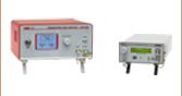
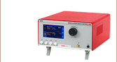
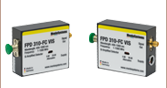
MX10A
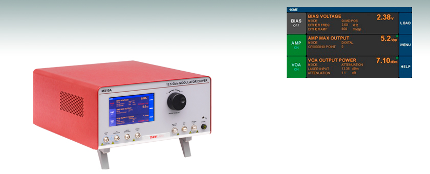
Modulator Driver for Operation up to 12.5 Gb/s
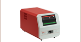
Touchscreen Interface


Please Wait
Click to Enlarge
Block Diagram of the Internal Setup of the MX10A and MX40A Modulator Drivers.
See the Operation tab for details.

Janis Valdmanis, Ph.D. Optics
Ultrafast Optoelectronics
General Manager
Got Questions?
Our engineers and expertise are here for you!
If you are not sure whether our catalog items meet your needs, we invite you to contact us. Or ask about a loan, so you can try them out for yourself, in your own lab. We can also support custom or OEM requirements you may have.
Just press the button, and we'll get back to you within the next business day.

Features
- Benchtop Drivers for LiNbO3 Electro-Optic Modulators
- High-Speed Digital Operation
- MX10A: 12.5 Gb/s Max System Bit Rate
- MX40A: 40 Gb/s Max System Bit Rate
- Analog (Linear) Operation
- MX10A: Up to 7 GHz Small Signal Bandwidth
- MX40A: Up to 20 GHz Small Signal Bandwidth
- RF Amplifier with Amplitude and Eye-Crossing Controls
- Fully Automatic or Manual Bias Control for Intensity Modulators
- Peak, Null, and Quadrature Set Points
- Dithered or Ditherless Operation
- Built-In Variable Optical Attenuator (VOA) for Automatic or Manual Power Control
- Control via Touchscreen Interface or Remotely using USB or RS-232 Connections
Thorlabs' High-Speed LiNbO3 Modulator Drivers provide control for fiber-coupled lithium-niobate electro-optic modulators. The operational wavelength range extends from 1250 nm to 1610 nm (O- through L-band), and the user may select from power calibration points at 1310 nm, 1550 nm, and 1590 nm using the touchscreen interface. These instruments are ideal for use either in an R&D laboratory or in a manufacturing environment for creating optical links, performing experiments requiring fast optical modulation, or testing modulators or other components.
These drivers are designed for use with LiNbO3 phase or intensity modulators and provide all the electronics necessary for biasing and RF driving. Depending on the model, each driver is compatible with modulators that can operate at up to speeds of 12.5 Gb/s or 40 Gb/s for digital operation or at a small signal bandwidth of up to 7 GHz or 20 GHz for analog operation. The internal circuitry enables bias control with peak, null, and quadrature set points. The drivers also include a series of power monitors at the laser input, modulator output, and final optical output, as well as a variable optical attenuator, for fully automatic monitoring and control of optical power along the entire optical path. See the Operation tab for more information on the system.
The MX10A and MX40A can be controlled in two ways. The simplest method is using the intuitive touchscreen interface, which gives the user complete control over all instrument functionality. These instruments can also be operated remotely via the RS-232 or USB ports on the back panel. The Operation tab describes graphical user interface (GUI) and user-customizable features, and we provide a remote control user guide and a remote control software tool (see the Software tab) for download.
The instruments featured here contain only the electronics for biasing and driving the modulators and do not include an intensity or phase modulator. For all-in-one instruments that include an intensity or phase modulator, modulator driver, and tunable laser, see our Reference Transmitters and our Optical Transmitters with Phase Modulators.
| Power and Environmental Specifications | ||
|---|---|---|
| Parameter | Min | Max |
| Main AC Voltage | 100 VAC | 250 VAC |
| Power Consumption | - | 60 VA |
| Line Frequency | 50 Hz | 60 Hz |
| Operating Temperature | 10 °C | 40 °C |
| Storage Temperature | 0 °C | 50 °C |
| Humiditya | 5% Relative Humidity | 85% Relative Humidity |
| Item # | MX10A | MX40A |
|---|---|---|
| System | ||
| Optical Input Power | 20 dBm (Maximum) 22 dBm (Absolute Max.) |
|
| External Laser Wavelength Range | 1250 - 1610 nm | |
| Power Calibration Points | 1310 nm, 1550 nm, and 1590 nm | |
| Maximum Bit Rate (Digital Signal) | 12.5 Gb/s | 40 Gb/s |
| Small Signal Bandwidtha | 7 GHz | 20 GHz |
| Low Frequency Cutoff | 100 kHz | |
| Amplifier RF Input (Linear Response)b | 100 mV (Maximum) | 120 mV (Maximum) |
| Amplifier RF Input (Digital Mode)c | 400 mV (Typical) 3.5 V (Maximum) 4 V (Absolute Max) |
400 mV (Typical) 4 V (Maximum) 6 V (Absolute Max) |
| Maximum Amplifier DC Input | ±15 V | ±10 V |
| Maximum Bias Voltage to Modulator | ±10 V (≥50 Ω Input Impedance) | |
| Internal Fiber | PM Ports: PM PANDA-Style Fiber SM Port: SMF-28-Compatible Fiber |
|
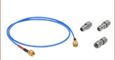
| Fiber Connectors | FC/PC, 2.0 mm Narrow Key | |
| Electrical Connectors | SMA Female | |
| Internal Amplifier | ||
| Rise/Fall Timed | 35 ps | 8 ps |
| RF Amplifier Gain | 34 dB | 30 dB |
| RF Amplifier Maximum Output Swing | 3 V - 7 V (Adjustable) | |
| Electrical Return Losse | -10 dB (Typical) | |
| Internal Control | ||
| Power Monitor Accuracy | ±0.5 dBm at Power Calibration Points | |
| Power Monitor Resolution | 0.01 dBm | |
| Power Monitor Insertion Loss (Typical) | 0.1 dB per Monitor | |
| VOA Insertion Loss (Typical) | 0.4 dB | |
| VOA Attenuation | 20 dB (Max) | |
| VOA Response Time | 1 s | |
System Overview
The block diagram below provides a basic illustration of the internal setup of the modulator drivers. The external laser is directed into the driver and through Monitor 1 before exiting to the external modulator. The output of the modulator then returns into the instrument and passes through the VOA-based power control system on its way to the output on the front panel. The drivers include a high-performance RF amplifier for driving the modulator. Automatic bias control is added for use with intensity modulators. The rear panel features output ports for several additional monitor and control functions.

Block Diagram of the Internal Setup of the MX10A and MX40A Modulator Drivers
Touchscreen Interface
These instruments can be fully controlled by using the resistive touchscreen display, which is sensitive to finger pressure or the tap of a plastic stylus. Additionally, the knob on the front panel of the housing can be used in place of the on-screen arrow buttons for quickly changing set-point values. Pressing (clicking) the knob will confirm a new set-point value.

Click to Enlarge
Main Menu (Home Screen) of the MX10A and MX40A
Home Screen
The home screen is organized in three main sections.
- Left Column:
- Buttons show the on/off status of the different instrument functions
- Tap a button to toggle the function on/off.
- Middle Column:
- Current operating parameters of each control function are shown.
- Tap in this column to access the Settings page for each function.
- Right Column:
- Buttons provide access to various utility and help functions.
- Tap to review and customize system settings..
The basic layout can be seen in the screenshots to the right. The green dot that appears in the upper-right of the center column panels indicates that those functions are stable. The dot will blink if that function is still stabilizing.

Click to Enlarge
System Wavelength Selection Screen
System Wavelength Setting
The System Wavelength may be selected on the Menu page, shown to the right. The choice of system wavelength specifies which calibration settings to apply to the intensity monitors in the modulator driver. The MX instruments can be used at wavelengths anywhere between 1250 nm and 1610 nm, but the power monitors are only calibrated at three main wavelengths: 1310 nm, 1550 nm, and 1590 nm. These wavelengths represent the centers of the O-Band, C-Band, and L-Band and therefore provide the user with accurate power readings at or near those wavelengths.
Click to Enlarge
Amplifier Settings Screen
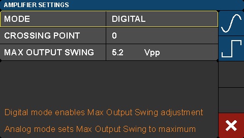
Amplifier Settings
Each modulator driver includes a high-performance RF amplifier that provides a fixed gain to a user-supplied input signal. Users can select analog or digital operating mode for the amplifier. Analog operation allows for maximum linear modulation with low distortion. In digital mode, both the output swing and crossing point can be adjusted by the user while the gain is held constant. This adjustment allows the user to optimize the bit-error-rate (BER) performance by adjusting the amplifier’s internal threshold levels.

Click to Enlarge
Bias Settings Screen
Bias Settings (For Use with Intensity Modulators Only)
When driving an intensity modulator, the MX10A and MX40A provide four modes for bias control. Users can select whether to use the peak, null, or quadrature point of the transfer function as the set point. Additionally, a manual mode allows the user to select any point of the transmission function to be used as the set point for the modulator bias.
These instruments can also provide bias control with or without a dither tone. For bias control with dither, users can select the amplitude and frequency that work best with their applications. For applications that require the highest SNR, the dither tone can be turned off. In this case, the bias will simply be held at the previous bias voltage. For longer term measurements, the Manual Constant Ratio mode provides another option for stabilizing the bias point. This mode operates by holding the ratio of modulator input light (Monitor 1 in the block diagram above) to modulator output light (Monitor 2) at a constant, user-set value.

Click to Enlarge
VOA Settings Screen
VOA Settings
On this screen, the user can control the optical output power via the Variable Optical Attenuator (VOA). The VOA can be operated in one of two modes: Constant Attenuation or Constant Output Power. In Constant Attenuation mode, the attenuation level between the output of the modulator and the output of the entire unit remains fixed, allowing power changes at the input to be transferred to the output. In Constant Output Power Mode, the final optical output power is held constant independent of the input fluctuations. In this mode, the VOA is effectively used as a power stabilizer.
Rear Panel
The rear panel provides additional utility functions such as the power monitor output, RS-232, and USB ports. The USB interface is currently used only for firmware upgrades that are made available on the Thorlabs website. Future revisions of the firmware will provide for remote control of the instrument’s functions.
Front Panel

Click to Enlarge
MX10A Front Panel
| Callout | Description |
|---|---|
| 1 | Touchscreen Display and Control |
| 2 | Value Adjustment Knob |
| 3 | Earth Ground Port for ESD Wrist Strap Banana Plug |
| 4a | Laser In for External Laser Source, Accepts PM Fiber with FC/PC Connector |
| 5a | Laser Output to Modulator Input, Accepts PM Fiber with FC/PC Connector |
| 6b | Return from Modulator Output, FC/PC Connector |
| 7b | Optical Out: Final Optical Output, FC/PC Connector |
| 8 | Amplifier RF Out: Signal to Modulator, SMA Female |
| 9 | Bias Output to Modulator, SMA Female |
| 10 | Amplifier RF In: Signal Input to Amplifier, SMA Female |
| 11 | On/Standby Button |
Back Panel

Click to Enlarge
MX10A Back Panel
| Callout | Description |
|---|---|
| 1a | I/O Control Port Outputs from Three Integrated Power Monitors |
| 2a | RS-232 Control Port |
| 3 | USB Port (Type B) |
| 4 | AC Power Cord Connector |
| 5 | Fuse Tray |
| 6 | AC Power Switch |
I/O DB15 Connector (Female)
The I/O connector provides analog outputs from the three power monitors.
| Pin | Description | Pin | Description |
|---|---|---|---|
| 1 | Power Monitor 1 | 9 | Analog Ground |
| 2 | Power Monitor 2 | 10 | Analog Ground |
| 3 | Power Monitor 3 | 11 | Reserved for Future Use |
| 4 | Reserved for Future Use | 12 | Reserved for Future Use |
| 5 | Analog Ground | 13 | Monitor 1 Gain Indicator |
| 6 | Analog Ground | 14 | Monitor 2 Gain Indicator |
| 7 | Analog Ground | 15 | Monitor 3 Gain Indicator |
| 8 | Analog Ground | - | - |
RS-232 Connector (Male)
The RS-232 connector is provided to support remote operation.
| Pin | Description |
|---|---|
| 1 | Not Connected |
| 2 | RS232 Input |
| 3 | RS232 Output |
| 4 | Not Connected |
| 5 | Digital Ground |
| 6 | Not Connected |
| 7 | Not Connected |
| 8 | Not Connected |
| 9 | Not Connected |
USB, Type B (Female)
The USB connector is provided for firmware upgrades and will support remote operation in the future.
Each Modulator Driver includes:
- Modulator Driver Main Unit
- Power Cord According to Local Supply (Determined by Ordering Location)
- 1.25 A, 250 VAC Fuse
- USB Type A to Type B Cable, 6' Long

Click to Enlarge
The GUI of the Remote Control Software Tool
Software for the MX10A and MX40A EO Modulator Drivers
Control the Modulator Drivers Remotely via Serial Commands
Serial commands sent to the MX10A or MX40A modulator drivers can control the functionality of the internal RF amplifier, EO modulator bias controller, and variable optical attenuator (VOA), as well as general system parameter settings. The commands can be sent from a computer running any operating system to the RS-232 port on the back panel of the modulator driver. Computers running Windows® 7, or later versions of the operating system, can send serial commands to the USB port on the back panel of the modulator driver. The touchscreen interface remains active while the modulator driver is controlled remotely. Descriptions of how to connect a controlling computer to the modulator driver, the serial command set, and descriptions of each command are included in the Remote Control User Guide.
Application Demonstrating GUI-Based Remote Control of the Modulator Drivers
The Remote Control Software Tool, which is available for download, is an example graphical user interface (GUI) provided for testing, demonstrating, and exploring the use of the different serial commands. This program is not required to operate the modulator driver remotely. It opens a connection to the laser source and sends commands in response to buttons clicked by users. Commands sent to the modulator driver, responses from it, and status information messages are logged to the three rectangular fields located beneath the buttons. Please see the Remote Control User Guide for more information. This program can be used as a basis for the development of custom applications. Please
Software
Version 1.8.7 (May 5, 2022)
Click on the link below to download the Remote Control Software Tool.

Firmware Update
Version 1.8.3 (January 13, 2020)
Click on the link below to download the latest firmware.


Janis Valdmanis, Ph.D. Optics
Ultrafast Optoelectronics
General Manager
Custom and OEM Options
When your application requirements are not met by our range of catalog products or their variety of user-configurable features, please contact me to discuss how we may serve your custom or OEM needs.
Request a Demo Unit
Explore the benefits of using a Thorlabs high-speed instrument in your setup and under your test conditions with a demo unit. Contact me for details.
![]()

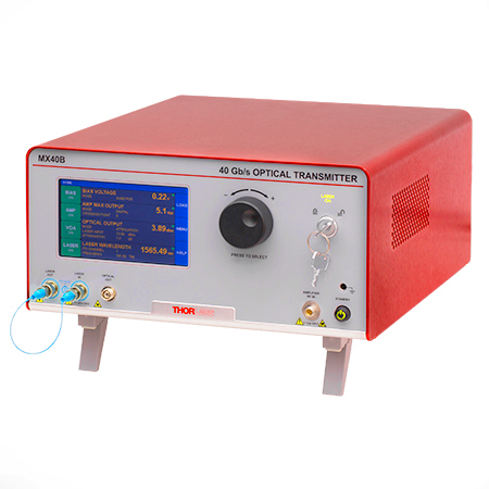
Click to Enlarge
The MX40B Digital Reference Transmitter
Design, Manufacturing, and Testing Capabilities
Thorlabs' Ultrafast Optoelectronics Team designs, develops, and manufactures high-speed components and instrumentation for a variety of photonics applications having frequency responses up to 110 GHz. Our extensive experience in high-speed photonics is supported by core expertise in RF/microwave design, optics, fiber optics, optomechanical design, and mixed-signal electronics. As a division of Thorlabs, a company with deep vertical integration and a portfolio of over 20,000 products, we are able to provide and support a wide selection of equipment and continually expand our offerings.
Our catalog and custom products include a range of integrated fiber-optic transmitters, modulator drivers and controllers, detectors, receivers, pulsed lasers, variable optical attenuators, and a variety of accessories. Beyond these products, we welcome opportunities to design and produce custom and OEM products that fall within our range of capabilities and expertise. Some of our key capabilities are:
- Detector and Receiver Design, to 70 GHz
- Fiber-Optic Transmitter Design, to 110 GHz
- RF & Microwave Design and Simulation
- Design of Fiber-Optic and Photonics Sub-Assemblies
- High-Speed Testing, to 110 GHz
- Micro-Assembly and Wire Bonding
- Hermetic Sealing of Microwave Modules
- Fiber Splicing of Assemblies
- Custom Laser Engraving
- Qualification Testing
Overview of Custom and Catalog Products
Our catalog product line includes a range of integrated fiber-optic transmitters, modulator drivers and controllers, detectors, pulsed lasers, and accessories. In addition to these, we offer related items, such as receivers and customized catalog products. The following sections give an overview of our spectrum of custom and catalog products, from fully integrated instruments to component-level modules.
Fiber-Optic Instruments
To meet a range of requirements, our fiber-optic instruments span a variety integration levels. Each complete transmitter includes a tunable laser, a modulator with driver amplifier and bias controller, full control of optical output power, and an intuitive touchscreen interface. The tunable lasers, modulator drivers, and modulator bias controllers are also available separately. These instruments have full remote control capability and can be addressed using serial commands sent from a PC.
- Fiber-Optic Transmitters, to 110 GHz
- Linear and Digital Transmitters
- Electrical-to-Optical Converters, to 110 GHz
- Modulator Drivers
- Modulator Bias Controllers
- C- and L-Band Tunable Lasers
Customization options include internal laser sources, operating wavelength ranges, optical fiber types, and amplifier types.
Fiber-Optic Components
Our component-level, custom and catalog fiber-optic products take advantage of our module design and hermetic sealing capability. Products include detectors with frequency responses up to 50 GHz, and we also specialize in developing fiber-optic receivers, operating up to and beyond 40 GHz, for instrumentation markets. Closely related products include our amplifier modules, which we offer upon request, variable optical attenuators, microwave cables, and cable accessories.
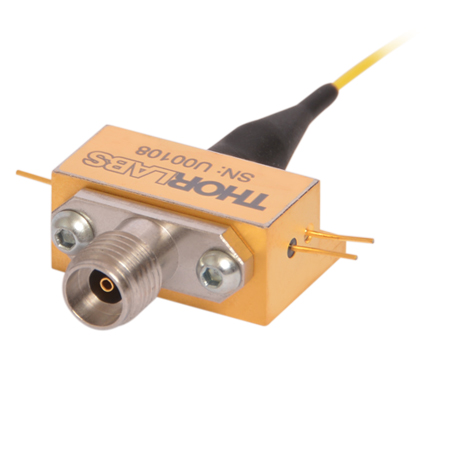
- Hermetically-Sealed Detectors, to 50 GHz
- Fiber-Optic Receivers, to 40 GHz
- Amplifier Modules
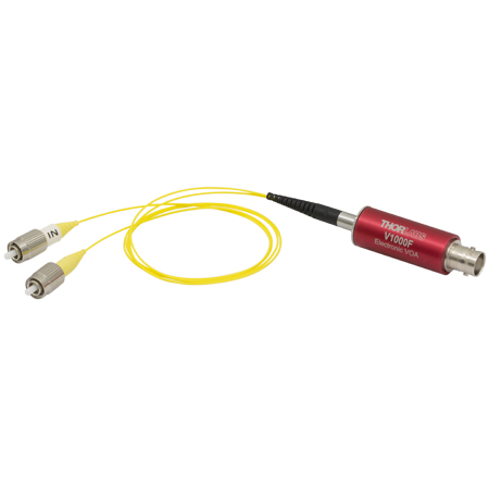
- Electronic Variable Optical Attenuators
- Microwave Cables and Accessories
Customization options include single mode and multimode optical fiber options, where applicable, and detectors optimized for time or frequency domain operation.
Free-Space Instruments
Our free-space instruments include detectors with frequency responses around 1 GHz and pulsed lasers. Our pulsed lasers generate variable-width, nanosecond-duration pulses, and a range of models with different wavelengths and optical output powers are offered. User-adjustable repetition rates and trigger in/out signals provide additional flexibility, and electronic delay-line products enable experimental synchronization of multiple lasers. We can also adapt our pulsed laser catalog offerings to provide gain-switching capability for the generation of pulses in the 100 ps range.
- Pulsed Lasers with Fixed 10 ns Pulse Duration
- Pulsed Lasers with Variable Pulse Width and Repetition Rates
- Electronic Delay Units to Synchronize NPL Series Pulsed Lasers
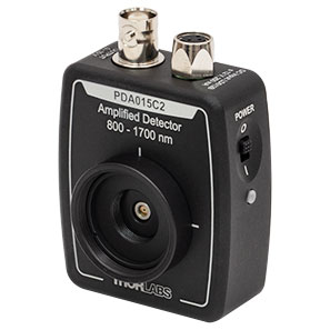
- Amplified Detectors
Customization options for the pulsed lasers include emission wavelength, optical output powers, and sub-nanosecond pulse widths.

| Posted Comments: | |
Aldo Apponi
(posted 2021-06-26 18:29:31.903) What is the cut-on frequency of the RF amplifiers in this product series? We may have a special need to modulate at both Communications rates of 10 GB/s, but also at very low frequencies as well---say a few 10s or 100s of kHz as well. YLohia
(posted 2021-06-28 11:25:17.0) Thank you for contacting Thorlabs. The low-frequency cut-off is specified on the "Specs" tab as 100 kHz. Unfortunately, a few 10s of kHz will not be a suitable application for these drivers. Aldo Apponi
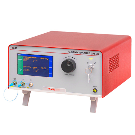
(posted 2021-06-26 14:56:05.01) Our application is polarization sensitive. What is the polarization output if coupled with your TLX1 tunable C-band laser? Is it possible to get these units with the PM fiber on the output of the EO modulator? YLohia
(posted 2021-06-28 11:25:16.0) The output of the TLX1 laser is linearly polarized (>= 18 dB PER) and aligned to the slow axis of the fiber (please see the Specs tab). Custom units of the MX10A and MX40A can be requested by using this link (https://www.thorlabs.com/ultrafastoptoelectronicfeedback.cfm) or the "Request Quote" button above. roptics
(posted 2016-05-12 14:36:37.483) This looks like a nice design is a 100 Gb/s version in the works? besembeson
(posted 2016-05-17 08:32:23.0) Response from Bweh at Thorlabs USA: Thanks for your interest. We are working on such higher bandwidth modulator drivers with matching amplifiers. I will contact you to further discuss your requirements. |
Choose Optical Transmitter by Application
- Beginning at the left side of the table, choose your desired system characteristics.
- Follow the table to the right and continue to select characteristics from the options within the same row as your previous selection.
- After reaching a Base Item #, choose a laser type. Your system's item # will be your base item # combined with the suffix for your laser type, e.g. MX40B-1310.
| Start Here | Follow the Table to the Right and Choose From These Options | Find Your System Here | ||||
|---|---|---|---|---|---|---|
| Modulator Type | Primary Application | Modulation Format | Speed | RF Input | Base Item # | Item # Suffix: Laser Type |
| Amplitude | Time Domain / Eye Diagram | Linear / 4-Level PAM4 | 32 GBaud | Differential | MX35D | No Suffix: C-Band Tunable Laser -LB: L-Band Tunable Laser -1310: 1310 nm Fixed Laser -850: 850 nm Fixed Lasera,b |
| Single Ended | MX35E | |||||
| 56 GBaud | → | MX65E | ||||
| Digital / 2-Level NRZ / OOK | 10 Gbps | → | MX10B | |||
| 40 Gbps | → | MX40B | ||||
| 56 Gbps | MX50E | |||||
| 56 Gbps | → | MX65E | ||||
| Frequency Domain / VNA | → | 40 GHz | → | MX40G | ||
| 70 GHz | → | MX70G | ||||
| 110 GHz | → | MX110G | ||||
| Phase | → | → | 10 Gbps | → | MX10C | |
| 40 Gbps | → | MX40C | ||||
Choose Optical Transmitter Instrument by Features
| Transmitter Instruments and Tunable Lasers | |||||||
|---|---|---|---|---|---|---|---|
| Item # | Speed | Internal Laser | Internal Modulator (Type) |
RF Amplifier (Type) |
Bias Controller |
Variable Optical Attenuator (VOA) |
Block Diagram |
| Automatic Bias Controller | |||||||
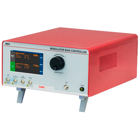
| MBX (770 - 980 nm) |
N/A | - | - | - |  |
||
| MBX2 (1250 - 1610 nm) |
N/A | - | - | - | |
||
| Tunable Telecom-Grade Laser Sources | |||||||
| TLX1 | N/A | C-Band, Tunable | - | - | - |  |
|
| TLX2 | N/A | L-Band, Tunable | |||||
| High-Speed Modulator Drivers | |||||||
| MX10A (1250 - 1610 nm) |
12.5 Gb/sa | - | - | Digital |  |
||
| MX40A (1250 - 1610 nm) |
40 Gb/sa | ||||||
| High-Speed Optical Transmitters | |||||||
| MX10B | 12.5 Gb/sa | C-Band, Tunable | Intensity | Digital | 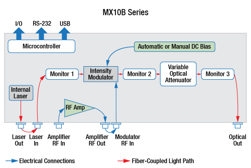 |
||
| MX10B-LB | 12.5 Gb/sa | L-Band, Tunable | |||||
| MX10B-1310 | 12.5 Gb/sa | 1310 nm, Fixed | |||||
| MX10C | 12.5 Gb/sa | C-Band, Tunable | Phase | Digital | - |  |
|
| MX10C-LB | 12.5 Gb/sa | L-Band, Tunable | |||||
| MX10C-1310 | 12.5 Gb/sa | 1310 nm, Fixed | |||||
| MX35E | 35 GHzb | C-Band, Tunable | Intensity | Linear |  |
||
| MX35E-LB | 35 GHzb | L-Band, Tunable | |||||
| MX35E-1310 | 35 GHzb | 1310 nm, Fixed | |||||
| MX35D | 35 GHzb | C-Band, Tunable | Intensity | Linear with Differential Input |
 |
||
| MX35D-LB | 35 GHzb | L-Band, Tunable | |||||
| MX35D-1310 | 35 GHzb | 1310 nm, Fixed | |||||
| MX40B | 40 Gb/sa | C-Band, Tunable | Intensity | Digital |  |
||
| MX40B-LB | 40 Gb/sa | L-Band, Tunable | |||||
| MX40B-1310 | 40 Gb/sa | 1310 nm, Fixed | |||||
| MX40C | 40 Gb/sa | C-Band, Tunable | Phase | Digital | - |  |
|
| MX40C-LB | 40 Gb/sa | L-Band, Tunable | |||||
| MX40C-1310 | 40 Gb/sa | 1310 nm, Fixed | |||||
| MX50E-850 | 50 GHzb | 852 nm, Fixed | Intensity | Linear | |||
| MX65E | 65 GHzb | C-Band, Tunable | Intensity | Linear |  |
||
| MX65E-LB | 65 GHzb | L-Band, Tunable | |||||
| MX65E-1310 | 65 GHzb | 1310 nm, Fixed | |||||
| E-O Converters for VNA Applications | |||||||
| MX40G | 40 GHzb | C-Band, Tunable | Intensity | - |  |
||
| MX40G-LB | 40 GHzb | L-Band, Tunable | |||||
| MX40G-850 | 40 GHzb | 850 nm, Fixed | |||||
| MX40G-1310 | 40 GHzb | 1310 nm, Fixed | |||||
| MX70G | 70 GHzb | C-Band, Tunable | Intensity | - | |||
| MX70G-LB | 70 GHzb | L-Band, Tunable | |||||
| MX70G-1310 | 70 GHzb | 1310 nm, Fixed | |||||
| MX70G-DB1 | 70 GHzb | C-Band, Tunable | Intensity | - |  |
||
| 1310 nm, Fixed | |||||||
| MX110G | 110 GHzb | C-Band, Tunable | Intensity | - |  |
||
| MX110G-1310 | 110 GHzb | 1310 nm, Fixed | |||||
The capabilities of Thorlabs' extensive range of transmitter instruments are summarized in the text and table below. All members of this product series share a similar interface, as well as a common remote control command set.
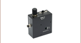
Automatic Bias Controller
Thorlabs' fully-featured automatic bias controller provides complete and precise control of DC bias and optical output power for any fiber-coupled LiNbO3 EO intensity modulator, regardless of signal speed. Automatic bias controllers are ideal for use within a customized setup that uses an external laser, intensity modulator, signal source, and RF amplifier.
Tunable Telecom-Grade Laser Sources
Emitting in the C-band or the L-band, these lasers have narrow typical linewidths of 10 kHz. A frequency dither option aids in stabilizing the laser wavelength, and the integrated variable optical attenuator (VOA) provides optical output power control. These lasers are tunable in 50 GHz steps across the ITU frequency grid, and feature a 1 MHz step size fine-tune capability, as well.
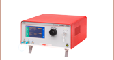
High-Speed Modulator Drivers
With an operational wavelength range of 1250 nm to 1610 nm, each modulator driver provides control for an external fiber-coupled LiNbO3 EO modulator. Each modulator driver includes an RF amplifier with amplitude and eye-crossing controls and accepts an external drive signal source. Models with integrated automatic bias controllers are offered for use with intensity EO modulators.
High-Speed Optical Transmitters
Designed to provide fully-integrated solutions for high-speed light modulation, these systems are built around a LiNbO3 intensity or phase modulator. The MX10B, MX40B, MX10C, and MX40C series of systems include a digital (limiting) RF amplifier, which offers fixed gain and an adjustable output voltage swing. The MX35E, MX50E, and MX65E series include a high-bandwidth linear (analog) RF amplifier, making it well suited for pulse amplitude modulation and related applications.
E-O Converters for VNA Applications
With our MX40G, MX70G, and MX110G series of E-O converters, any E-E vector network analyzer can be used to perform optical testing up to 40 GHz, 70 GHz, and 110 GHz respectively. The E-O converter is a fully-integrated solution that includes a laser, a modulator, and bias control.