 Products Home / Lasers / Coherent Sources / Fiber-Coupled Laser Sources / 4-Channel Laser/SLD Source, TEC Stabilized, 1 A per Channel
4-Channel Laser/SLD Source, TEC Stabilized, 1 A per Channel
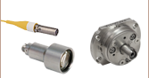
- 4 Laser or SLD Output Channels with FC/PC or FC/APC Connectors
- TEC and Constant-Current Source for Each Channel
- Stable, Low-Noise Output
- 49 Wavelength/Power/Source Type Combinations
Available
MCLS2-CUSTOM
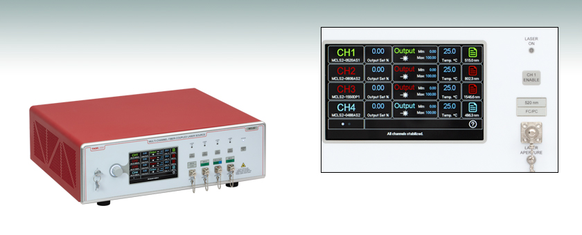
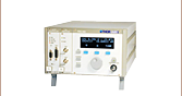
4-Channel Laser/SLD Source, TEC Stabilized, 1 A per Channel
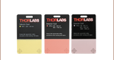
The touchscreen above shows the four channels of the MCLS2 laser/SLD source.


Please Wait
| Item # | MCLS2-CUSTOM |
|---|---|
| Temperature Adjust Range | 20.00 to 30.00 °C |
| Temperature Set Point Resolution | Default ±0.1 °C (Available Range 0.1 to 1%) |
| Output Set Point Resolution | Default ±0.1 °C (Available Range 0.01 to 5%) |
| Noise | <0.5% Typical (Source Dependent) |
| Rise/Fall Time | <1 µs |
| Support Documents |
Features
- Up to 4 User-Configurable Channels with Independent FC/PC or FC/APC Fiber-Coupled Outputs
- Three Different Light Source Types Available:
- Fabry-Perot Lasers
- Distributed Feedback (DFB) Lasers
- Superluminescent Diodes (SLDs)
- 49 Wavelength/Power/Source Type Combinations Available with up to 700 mW Output Power
- Independent TEC for Each Channel Gives High Temperature Stability
- USB Interface and Software Package for Remote Operation
Thorlabs' 4-Channel Laser/SLD Source can be configured with up to four user-selected laser diodes or SLDs, each with its own independent TEC. Available laser and SLD options, outlined in the table below, are suitable for applications including fluorescence microscopy, reflective imaging, metrology, telecom, and infrared spectroscopy. Our wavelength offerings span 406 to 2000 nm and can be placed in the source in any combination. This benchtop device allows more than one channel to be turned on simultaneously.
Each diode is operated from an independent, high-precision, low-noise, constant-current source and temperature control unit. The device includes a microcontroller to fully control the laser's optical power and temperature as well as monitors the system for fault conditions. A touchscreen LCD interface allows the user to view and set the current and temperature independently for each laser or SLD. The display indicates the channel number selected, the output wavelength of the source, the operating power calculated from the source's monitor diode (if applicable), and the actual temperature to which the source is set.
The MCLS2-CUSTOM source includes a USB connection that allows remote enabling, power adjustment, and temperature adjustment. On the rear panel of the unit, modulation inputs are available to independently modulate each diode's output with an externally generated waveform. To prevent damage, the microcontroller will disable the output if the sum of the analog input and internal set point exceeds the laser limits.
Safety
While most light source options for the MCLS2-CUSTOM system fall within the class 3B laser rating or lower, the system was fully designed to meet laser class 4 requirements. There is an interlock located on the rear panel that must be shorted in order for any output to be enabled. This can easily be configured to be triggered by doors to disable the lasers or SLDs in unsafe conditions. The power switch is a keylock system to prevent accidental or unwanted use. Each source has its own enable button allowing the user to choose which light sources to enable, as well as an ENABLE ALL button that can be used to enable all sources at once. Each channel includes a green LED indicator to easily determine its current state. There is a 5 second delay before the laser(s) or SLD(s) turn on, during which the channel enable LED(s) blink rapidly. The laser or SLD must be turned off before connecting or disconnecting a fiber to the output ports, particularly for powers above 10 mW.
In the Box
The MCLS2-CUSTOM 4-Channel Laser/SLD Source includes a universal power supply allowing operation over 85 - 264 VAC without the need for selecting the line voltage. The fuse access is conveniently located on the rear panel. This unit is supplied with a region-specific U.S. or standard European line cord, the pre-configured laser/SLD source with all selected light sources installed, and the manual.
Below is a list of available lasers and SLDs listed by wavelength and showing the corresponding minimum output power and pigtail fiber type. To discuss potential custom wavelengths and configurations not available below, please contact Tech Support. Please use the configurator below to select the pigtails and locations you would like.
Note: An MCLS2-CUSTOM unit must be purchased with at least one pigtail installed, and the channels of the unit must be filled in order. In other words, a laser or SLD for Channel 1 must be selected before a laser or SLD for Channel 2, Channel 2 before Channel 3, and Channel 3 before Channel 4. If you leave a subsequent channel blank, then the unit will be shipped without a laser or SLD in that channel. Subsequent empty channels can be filled by Thorlabs at a later date. Please contact Tech Support prior to sending your unit back to us.
The laser diodes and SLDs below are not available for purchase separately from the MCLS2-CUSTOM 4-Channel Laser/SLD Source; for users who would like to purchase a fiber-coupled laser diode or SLD separately, we offer a wide selection of pigtailed laser diodes in TO-can and butterfly packages, as well as SLDs in TO-can and butterfly packages.
| System | |
|---|---|
| Power Supply Type | Switch Mode AC/DC |
| Input Voltage | 85 - 264 VAC, 50 - 60 Hz |
| Power Rating | 130 VA |
| Fuse Type | IEC60127-2/3 (1.25 A, 250 V, Slow Blow Type 'T') |
| Operating Temperature Range | 20 to 30 °C |
| Storage Temperature | 0 to 85 °C |
| Physical Features | |
|---|---|
| Dimensions | 15.70" x 17.01" x 5.90" (398.8 mm x 432.1 mm x 149.9 mm) |
| Weight | 17.6 lbs (8.0 kg) |
| Power On | Key Switch |
| Fiber Ports | Dependent on Selected Light Sources |
| Modulation Input Connectors | BNC |
| Interlock | 2.5 Mono Phono Jack |
| Display | 5" TFT LCD Touchscreen |
| Adjustment Controls | Control Knob with LED Status Ring |
| USB Port Type | USB 2.0 Type-B |
| General Specifications | ||
|---|---|---|
| Output Characteristics | ||
| Laser Output Adjustment Resolution | Default: 0.01% (Available Range: 0.01 to 5%) | |
| Laser Adjustment Range | Default | 0% to Max |
| Option | Laser Threshold (Factory Set) to Max | |
| Performance Specifications | ||
| Temperature Adjustment Range | 20.00 to 30.00 °C | |
| Temperature Set Point Resolution | Default: 0.1 °C (Available Range: 0.1 to 1%) | |
| Noise | <0.5% Typical (Source Dependent) | |
| Rise Time/Fall Time | <1 µsec | |
| Modulation Input | 0 - 5 V = 0 - 100% Output | |
| Modulation Bandwidth | 200 kHz Full Depth of Modulation | |
| Modulation Input Characteristics | ||
| Modulation Input Connector | BNC | |
| Modulation Input Impedance | 1 kΩ | |
| 406 - 730 nm Laser Source Options |
|---|
| 785 - 976 nm Laser Source Options |
|---|
| 1064 - 2000 nm Laser Source Options |
|---|
| Super Luminescent Diode Source Options |
|---|
Please see the manual for in-depth operating instructions. A printed copy of this manual is included with each MCLS2-CUSTOM Laser/SLD Source. For information on the housing features referenced below, please see the Front and Back Panels tab.

Click to Enlarge
Figure 1. Front Panel

Click to Enlarge
Figure 2. Home Screen

Click to Enlarge
Figure 3. Profiles Menu

Click to Enlarge
Figure 4. Settings Menu

Click to Enlarge
Figure 5. Temperature Popup Screen
Turning On the Source
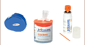
Before using the source, it is important to ensure that the connectors and fiber patch cables being used are clean and free from damage. To turn on the MCLS2-CUSTOM Laser/SLD Source, insert the key into the main power switch and turn it clockwise. The LCD display should show "Thorlabs" across the screen. Make sure the interlock input is short-circuited; detailed instructions can be found below. Each light source has an individual button that can be pressed and released to activate that source, while an "Enable All" button can be used to activate all light sources simultaneously (Figure 1). There will be an approximately 5 second delay before the laser(s) or SLD(s) turns on, during which the channel enable LED(s) will blink rapidly.
Touchscreen LCD Display and Control Knob
Thorlabs' 4-Channel, Fiber-Coupled, Customizable Laser/SLD Source uses a touchscreen LCD interface and a rotary control knob with an LED indicator ring to access and display information, as well as make system adjustments. Adjustable parameters can be selected with a single tap on the display over the desired parameter. The Home Screen for the 4-channel source is shown to the right (Figure 2), displaying the output setpoint, output limits, and temperature for each light source in its corresponding row. Selecting the document icon in the last column will open a Source Specifications sub-menu, which contains information about the selected light source including the wavelength and maximum power.
In the bottom left of the Home Screen is a box with two dots; selecting the right dot will open the Profiles menu (Figure 3), allowing the user to save the current settings of the laser or SLD source or load a previously saved profile. From this menu, pressing the gear icon in the lower left will bring up the Settings menu (Figure 4). The Settings menu has four tabs, which allow the display settings, knob settings, and systems settings to be adjusted, with the final tab displaying system information such as serial numbers and firmware versions.
Adjusting the Source Output Power and Temperature
From the Home Screen of the MCLS2-CUSTOM Laser/SLD Source, each row provides access to the menus and parameters of a single light source, with the top row dedicated to Channel 1 and the bottom row dedicated to Channel 4. To adjust a parameter (either the output power or the temperature), simply tap on the desired parameter and adjust the control knob until the desired value is shown. The increment with which the control knob modifies the output power and temperature can be individually selected and modified by accessing the Settings menu.
Alternatively, the parameter can be double tapped to bring up a popup keypad screen to allow the direct adjustment of the value, as shown in Figure 5. Selecting the check icon in the upper right corner of the number keypad will set the entered value without closing the window. This screen also has a touchscreen value bar on the left side, which can be slid up and down to adjust the parameter. The plus and minus signs, above and below the bar respectively, will increase or decrease the value of the parameter by one. A back arrow to the left of the parameter name at the top of the screen will return the user to the previous screen.
It should be noted that the Output Set parameter allows the user to select an output power from 0% to 100% of the maximum output power for a given light source. Each source will have its own scaling and behavior; the Source Specifications menu for each light source provides information on the maximum output power. The Temperature parameter modifies the temperature setpoint and can be adjusted from 20° C to 30 °C. By default, this parameter will display the set temperature, but this can be modified in the General Settings menu to instead display the measured temperature for the light source.
Modulating the Source Output
There are four BNC connectors on the back panel that can be used with a 0 - 5 V input signal to modulate the output of the light sources or set the outputs remotely. The 5 V maximum input corresponds to the maximum output power for each channel, with the input being additive with the internal source setpoint. If too much voltage is applied, internal current limiting will prevent damage to the light source, which will be immediately disabled. There are two main methods of modulation available: modulation from "Standby" operation or modulation with an internal offset.
To modulate from Standby operation, the light source is enabled and the output set to 0%. This allows utilization of the full 0 - 5 V input range, but requires a minimum DC offset in the signal to operate above the threshold current of a given source. This offset can be determined by slowly increasing the input voltage until a large power jump is observed in the output signal. The second method of operation requires setting the output of the light source to a desired minimum, as described above, or by utilizing the Threshold mode of the laser or SLD source and increasing the output by a single step. To calibrate the input, set the light source to the desired minimum and apply a DC voltage to the modulation input, slowly increasing the voltage until the system disables. This provides a maximum allowable voltage for that channel, which should be a similar percentage of the total voltage as the remaining output range of the light source when using Threshold mode (e.g. if threshold is at 25% output, the maximum modulating voltage with be 75% of the 5 V range, or 3.75 V).
Making the Safety Interlock Connections
The MCLS2-CUSTOM Laser/SLD Source is equipped with a remote interlock connector located on the rear panel. All units have this feature regardless of their FDA and IEC classifications. A short circuit must be applied across the terminals of the remote interlock connector for the source to be enabled. All units are configured with a shorting device installed in the Interlock connector, which if left in will allow the unit to operate normally as described above. This interlock connector is made available to the user to allow the connection of a remote-actuated switch (i.e., an open door indicator) to the source. A normally open switch must be used, which when closed will allow the unit to be enabled. Once the switch is in an open state, the source will automatically shut down. If the switch returns to a closed condition, the MCLS2-CUSTOM source must be re-enabled at the unit as described above. Details about the electrical specifications for the interlock input are found in the table below.
Interlock Mating Connector
| Specification | Value |
|---|---|
| Type of Mating Connector | 2.5 mm Mono Phono Jack |
| Open Circuit Voltage | +5 VDC with Respect to Chassis Ground |
| Short Circuit Current | 10.0 mA DC |
| Interlock Switch Requirementa | Must be Normally Open Dry Contacts |
Front Panel
Back Panel


| Callout | Description |
|---|---|
| 1 | Control Knob with LED Status Ring |
| 2 | Channel Enable Button (5 Places) |
| 3 | Laser Indicator Light (4 Places) |
| 4 | System Status Indicator Light |
| 5 | Main Power Key Switch |
| 6 | Touchscreen Display |
| 7 | Light Source Output (4 Places) |
| 8 | Fiber Output Cap (4 Places) |
| Callout | Description |
|---|---|
| 1 | Cooling Vent (2 Places) |
| 2 | Remote Interlock Input |
| 3 | AC Mains Power Plug with Fuse Drawer |
| 4 | Modulation Inputs (4 Places) |
| 5 | USB 2.0 Type B Port |
Software
Version 1.0
Software package to operate Thorlabs' MCLS2-CUSTOM 4-Channel Laser/SLD Source, including Thorlabs Device SDK v2.0, Thorlabs MCLS2-CUSTOM Control Softwware v1.0, Thorlabs xPlatform Software v1.2.0, and Thorlabs RS232 Driver v6.1.0.0
| Posted Comments: | |
| No Comments Posted |