 Products Home
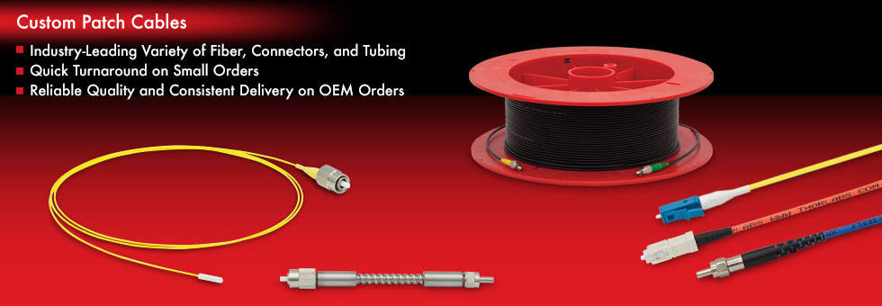
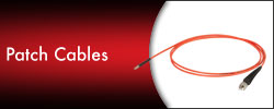
Custom Fiber Optic Patch Cables

Please Wait

Thorlabs stocks the largest selection of single mode and multimode optical fibers in the photonics industry. If our selection of stocked patch cables does not meet your needs, we also offer custom patch cable services. Please use the form below to build and order your custom cable. If you find your needs are not met by the options in the form below, please contact us and we will design a specialty cable to meet your needs.
Fast Turnaround Service
Need a cable right away to finish your project? If your order is placed before 2 PM EST weekdays* and the order request meets the following criteria, we will manufacture and ship them the same day (PM cables ship in 2 days):
- Total order request is for five or fewer SM or MM cables
- Each individual cable has a maximum length of 20 meters
Please note that certain custom cables, such as those utilizing epoxies with longer cure times or incorporating high-power connectors, require a longer assembly time and hence cannot be shipped same day. In those instances, the quoted lead time will be longer.
*Holiday exceptions apply. Please note that our custom patch cables are manufactured in the United States, which observes the following holidays: New Year's Day, Martin Luther King Jr. Day, Memorial Day, the 4th of July, Labor Day, Thanksgiving, and Christmas. At these times, please contact your local sales office for a confirmed production timeline.
OEM Patch Cables
We offer scheduled deliveries, competitive pricing, account support, and kanban stocking agreements. Please contact us with any questions you may have so we can better meet your OEM needs.
Fiber Optic Cable Structure
General Fiber Information
A fiber optic cable is made of 5 main parts, labeled in the figure to the right. The core, made of glass or plastic, provides the path for light propagation. Larger core sizes allow a greater amount of light, or a larger beam diameter, to enter the fiber. The numerical aperture (NA) of the core determines the range of incident angles the fiber can accept and still perform within its specified range. The cladding prevents light from exiting the core and being absorbed by the rest of the cable. The coating, or buffer, protects the core and cladding and provides strength. The next layer of the cable is a material, such as Kevlar, that reinforces the cable and helps prevent damage due to stress. The entire package is then encased in a jacket. This outer jacket provides one last layer of protection and also adds strength to the fiber. The jacket is typically colored to help the user determine what type of optical fiber is in the cable.
Thorlabs follows the industry standard in jacket coloration. We use a yellow jacket for our Single Mode (SM) fibers, an orange jacket for our Multimode (MM) fibers, and a blue jacket for our Polarization Maintaining (PM) fibers. Our custom patch cables can be made with any jacket color / fiber combination. Some Ø900 µm jackets are avaliable only in lengths up to a certain maximum as shown in the table below.
| Jacket Lengthsa | |||||
|---|---|---|---|---|---|
| Item # | FT900Y | FT900SM-BLUE | FT900KY | FT900KB | FT900KK |
| Maximum Length | <5 m | <3 m | <10 m | <10 m | <10 m |
Click to Enlarge
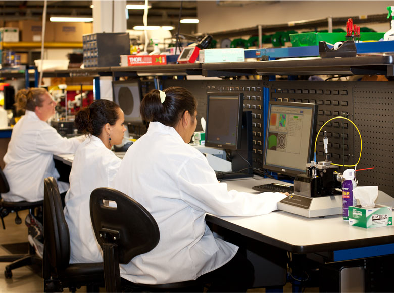
Patch Cable Inspection at Thorlabs in Newton, NJ
Building Your Custom Patch Cable
Have you looked through our broad selection of stocked patch cables to see if one of them meets your needs? If none of the stocked options are what you are looking for, a custom cable can be manufactured.
Select a Fiber
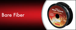
Thorlabs offers four major types of fiber: Single Mode (SM), Multimode (MM), Polarization Maintaining (PM), and Doped. Each fiber type is explained in detail below. You will also find a complete list of all the fibers that we offer for our custom patch cables along with key specifications that may help you decide which fiber is best for your application. We sell all of these fibers individually on our website as well, along with a wide variety of others. Click here to view all of the fiber options Thorlabs offers. Please contact Tech Support if you have any other questions about our fiber.
Light Propagation Down Single Mode Fiber
Single Mode (SM) Fiber
SM fiber has small core sizes that only allow one mode, or ray, to propagate through the fiber. The mode defines how the light travels through space. Light propagates along the axis of the fiber in this single mode (see drawing to the right). In SM fiber, waves have the same mode but different frequencies. This type of fiber is useful in situations where the integrity of the incident pulse of light needs to be retained over long distances. SM fiber offers high bandwidth and low modal dispersion.
Photosensitive SM Fiber
Photosensitive single mode fiber is designed to provide high photosensitivity for UV radiation. These fibers offer lower splice loss than standard SM fibers and are suitable for a range of applications. For more information about these fibers, click here.
| Photosensitive SM Fiber Options |
|---|
| SM Fiber Options |
|---|
* Cladding: Ø80 µm
** Ø900 µm Jacket
| Ultra High NA SM Fiber Options |
|---|
Light Propagation Down Step-Index Multimode Fiber
Light Propagation Down Graded-Index Multimode Fiber
Multimode (MM) Fiber
The larger core diameters of multimode (MM) fiber allow for the propagation of more than one mode. Light not only propagates along the axis of the fiber, as in SM fiber, but also travels away from the axis toward the cladding (see animations to the right). The total internal reflection that occurs at the core-cladding boundary helps reflect the light back towards the fiber axis. MM fiber tends to have a higher NA and larger core sizes than SM fiber, which allows it to gather larger beams of light at greater incident angles. It has lower bandwidth than SM fiber and is susceptible to modal dispersion.
Modal dispersion is a distortion of the incident light pulse caused by the fact that the propagation velocity of the different modes varies. Due to the “zigzag” path the modes take to travel down the fiber, the modes that zigzag more take longer to reach the end than those that travel in a straighter path. When all modes, both fast and slow, combine again at the other end of the fiber, the pulse is widened.
There are two main types of MM fiber: Step Index and Graded Index. The core in a step-index fiber has a uniform refractive index throughout. There is a sharp decrease in refractive index at the core-cladding boundary where the cladding refractive index is lower than that of the core. This results in the modes traveling down the fiber in a very jagged path (see animation to the right). Step-index fiber is generally made by doping the fiber with another material.
The refractive index of the core in a graded-index fiber decreases as the distance to the center of the core increases. This results in a much smaller change in the refractive indice at the core-cladding interface. The smoother transition causes the modes to travel in sinusoidal paths down the fiber (see animation to the right). Graded-index fibers have much lower modal dispersion than step-index fibers. The parabolic wave profile of the modes continuously re-focuses the rays. Those traveling straight down the center of the fiber travel much slower than those traveling in a more sinusoidal path due to the differences in refractive index. The resulting pulse is less spread out and very close in profile to the incident one.
Solarization-Resistant MM Fiber
Solarization-Resistant multimode fiber exhibits impressive performance and transmission from the UV to the NIR (180 to 1150 nm). With exceptional UV radiation resistance compared to standard fibers, these multimode fibers are ideal for use in applications such as spectroscopy for pollution analysis and chemical processing, UV photolithography, and medical diagnostics. The polyimide buffer allows this fiber to be used at temperatures up to 300 °C. For more information about these fibers, click here.
| High OH Step-Index MM Fiber Options |
|---|
| Graded-Index MM Fiber Options |
|---|
| Low OH Step-Index MM Fiber Options |
|---|
| Solarization Resistant Step-Index MM Fiber Options |
|---|
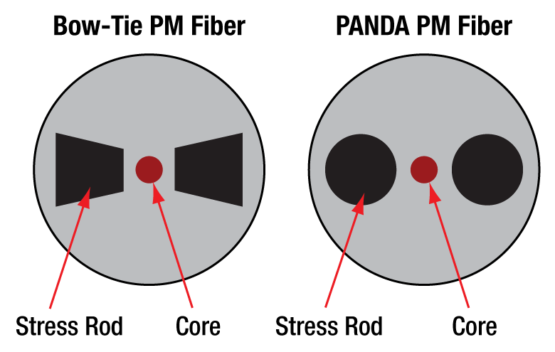
Polarization-Maintaining (PM) Fiber
The polarization of incident light is maintained during propagation through polarization-maintaining (PM) fiber. There are many types of PM fibers, but they all work the same way: stress is induced in the core via rods within the cladding. The stress aligns the fiber, and the light, to a particular polarization. Thorlabs offers two types of PM fiber: PANDA style and Bow-Tie style. The types are named for the shape of the stress rods incorporated into the fiber (see drawing to the right). PM fiber is used in fiber optic sensing, interferometry, and quantum key distribution. It is also commonly found in telecommunications applications connecting a laser source and a modulator. PM fiber has higher attenuation than SM and MM fibers.
It is important to note PM fiber does not polarize the incident light; rather, it just maintains the existing polarization of the light that is aligned with the stress rods. The fiber key is aligned during the manufacturing process to ensure high-quality output, as evidenced by the polarization extinction ratio (PER). A higher PER indicates that the light exiting the fiber has a polarization that is more consistent with that of what entered.
| Bow-Tie Style PM Fiber Options |
|---|
| Photosensitive PM Fiber Options |
|---|
| PANDA Style PM Fiber Options |
|---|
| Polarizing Fiber Optionsa |
|---|
| Spun Fiber Optionsa |
|---|
Doped Fiber
| Erbium-Doped SM Fiber Options |
|---|
Erbium-Doped SM Fiber
Our wide range of highly doped erbium fibers are suitable for fiber lasers and amplifiers operating in the 1530 to 1610 nm wavelength region. These fibers are utilized in a broad range of applications, ranging from telecommunication amplifiers (EDFAs) to high-power PON/CATV boosters and ultra-short pulse amplifiers used in instrumentation, industrial, and medical applications. For more information about these fibers, click here.
| Double Clad Ytterbium-Doped MM Fiber Options |
|---|
Ytterbium-Doped MM Fiber
Thorlabs offers state-of-the-art Ytterbium doped optical fibers for optical amplifiers, ASE light sources, and high-power pulsed and CW fiber laser applications. These fibers are fabricated using the latest doped fiber production technology. For more information about these fibers, please click here.
| Passive Double Clad Fiber Options |
|---|
Passive Double Clad Fiber
Thorlabs' passive large-mode-area (LMA) fibers are matched to the core diameters and numerical apertures of their active counterparts to maintain excellent beam quality throughout fiber laser or amplifier systems. The outer cladding diameter is designed to "round" the shaped active fibers, thereby achieving low pump coupling loss from passive to active fibers. The passive fibers are coated with low-index fluoroacrylate enabling active fibers to be pumped through them. For more information about these fibers, click here.
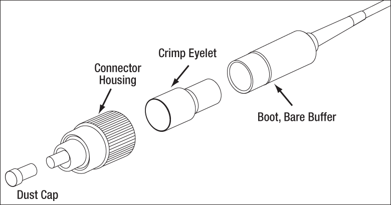
Choose a Connector
A connector terminates the end of an optical fiber and enables quick, easy connection and disconnection. The connectors mechanically couple and align the cores of the fibers so that light can pass from one to the other unobstructed. Thorlabs offers a flat-cleave option as well as 6 narrow key connectors for our Custom Patch Cables.
Flat-Cleave
A flat-cleave is a carefully controlled break in the fiber perpendicular to the fiber axis, resulting in a flat end face. No connector is attached to the fiber. A flat-cleave allows for bare fiber connection. Flat-Cleaves are ideal for mechanical or fusion splicing or free space applications without the use of a connector.
Scissor Cut
A scissor cut is a very quick cut that will not produce an even output or splice surface on the end of the fiber. This cut is ideal for the user who is proficient in cleaving fibers or intend to terminate a fiber with their own connector. The end of a scissor cut fiber must be cleaved and connectorized before it can be used.
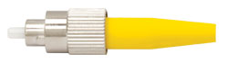
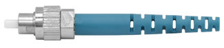
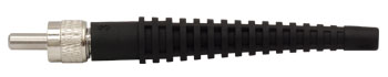
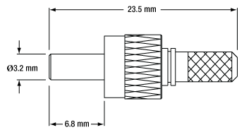
FC/PC Connectors
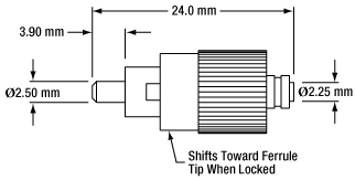
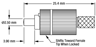
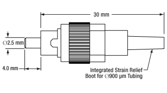
The threaded FC/PC connector is designed for high vibration environments. The "PC" stands for "physical contact" because this connector allows the fibers' surfaces to be in direct contact with each other at the connector interface. The ceramic or stainless steel ferrule, or end, of an FC/PC connector is spring loaded to control the force on the fiber as the connector is screwed into its port.
Single Mode FC/PC Connectors
Our single mode (SM) FC/PC connector features a pre-radiused (R20 mm) ceramic ferrule to help minimize back reflections. The SM FC/PC connector has a hole size tolerance of +1/-0 µm and a maximum concentricity of 1 µm.
Multimode FC/PC Connectors
Our multimode (MM) FC/PC connector has a precision-drilled bore to match the fiber diameter and a maximum concentricity of 3 µm.
Polarization-Maintaining FC/PC Connectors
For Polarization-Maintaining (PM) fibers, we offer a FC connector with a continuously adjustable key to allow you to rotate the back of the connector to align to the slow or fast axis of the fiber. Once the connector is aligned, you can lock it in place with a drop of superglue. If you purchase a PM fiber cable that is aligned by us, the connector key will be aligned to your specification.
FC/APC Connectors
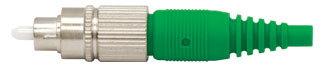
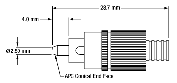
This connector has the same basic design as the FC/PC connector, but the fiber end is polished at an angle. This “Angled Physical Contact” (APC) interface prevents light reflected at the fiber-fiber junction from traveling back up the fiber. FC/APC connectors only mate properly with other FC/APC connectors. Mating FC/APC with any other connector results in high insertion loss. These connectors minimize back reflections but have a higher insertion loss than their FC/PC counterparts.
All of our FC/APC connectors offer a minimum back reflection of -65 dB due to the nature of the APC end. Thorlabs' APC connectors are distinguished by the use of a green strain relief boot.
SMA Connectors
Our subminiature version A (SMA) connectors are used for large core, multimode fibers. These connectors are threaded like our FC/PC and FC/APC connectors. We stock SMA connectors for fibers with cladding diameters ranging from 125 to 1580 µm.
ST® Connectors
Straight Tip (ST) connectors have a bayonet-style mount that allows for quick connects and disconnects but does not seat the fiber as well as other connections.
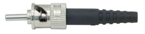
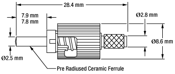
Our single mode (SM) ST connector features a ceramic ferrule with a pre-radiused tip (R20 mm) to minimize back reflections. The ST connectors feature a concentricity of maximum 1 µm.
We also carry ST-style connectors designed for multimode (MM) applications. Our standard connectors have a bore size of 140 µm but we also carry a full supply of drilled conectors to meet custom requirements. These connectors feature a maximum concentricity of 1 µm.
*ST® is a registered trademark of Lucent Technologies, Inc.
SC Connectors
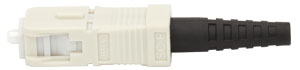
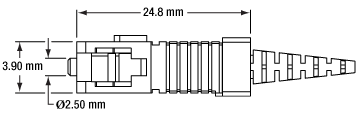
Subscriber Connector (SC) connectors are snap-in connectors that are easy and quick to use. Our SC-style connectors, which have a bore size of Ø125 µm, feature a pre-radiused (R20 mm) ceramic ferrule to help minimize back reflections.
LC Connectors
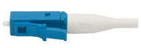
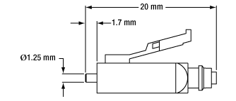
Lucent Connectors (LC) are similar to SC connectors but contain ferrules that are half the size of those found on SC connectors. We stock LC connectors for single mode fibers. Multimode LC connectors for fiber claddings up to Ø127 µm are available upon request. Due to their small size, they are ideal for situations where a large number of connectors are used in a small space.


| Posted Comments: | |
Kent Ramthun
(posted 2024-04-15 17:18:44.65) Can you make an Armored patch cable 30m long?
Would like PM980 fiber with FC-PC on one end and FC-APC on opposite end. jpolaris
(posted 2024-04-22 06:28:26.0) Thank you for contacting Thorlabs. Requests for customizations such as this can be made by emailing us at techsupport@thorlabs.com. I have reached out to you directly to discuss the feasibility of this request. Shreyas Rajebahadur
(posted 2024-02-27 10:34:33.713) Hello,
Would you be able to make a custom patch cable with the follow specs:
Connectors: High power SMA to high power FC/APC.
Fiber code- FG200LCC.
Length- 2m
Thanks jdelia
(posted 2024-03-04 11:42:47.0) Thank you for contacting Thorlabs. We unfortunately do not offer FC/APC connectors with a bore large enough for a 200 um diameter fiber, nor do we offer FC/APC connectors specifically designed for high powers. I have reached out to you directly to discuss your application. Alasdair Taylor
(posted 2023-08-08 14:48:27.523) Hello, Am looking to get a PM custom fiber with the metal jacket and a panel through mount to terminate the metal jacket, with a non-jacketed fibre on the 'inside'. The metal part will be outside the system and thus needs the protection and I intend to splice the inner part so it does not need a connector. The metal jacket needs an FC/APC.
Best
Alasdair cdolbashian
(posted 2023-08-16 12:21:50.0) Thank you for reaching out to us with this request! For custom requests which can't be configured with our "custom fiber configurator" web tool, please reach out to our custom team at techsales@thorlabs.com. I have reached out to you to clarify the specific configuration in which you are attempting to achieve. Lorenzo Lavista
(posted 2023-08-02 08:42:10.693) Hi, I wanted to know if it was possible to have a costumized FT1500UMT fiber only 30 cm long. Thanks jdelia
(posted 2023-08-02 02:15:26.0) Thank you for reaching out, Lorenzo. Yes, this is possible. You can configure this cable using our Custom Patch Cable Configurator located here: https://www.thorlabs.com/newgrouppage9.cfm?objectgroup_id=2410. Ben Routley
(posted 2023-07-18 16:33:28.653) Hi,
Do you still offer custom patch cables using HB1060Z fiber? cdolbashian
(posted 2023-07-21 03:07:34.0) Thank you for reaching out to us with this inquiry! We do still indeed offer patch cables with these fibers. Please feel free to email us at techsales@thorlabs.com if you are interested in such a configuration. Kenny Huang
(posted 2023-05-08 19:14:01.12) Hi there. I had customized a step index multimode fiber for OCT project to directed my SLD light source with wavelength 950~1050nm into spectrometer, but it was weird that fibers always induced large noise on spectrum. However, this issue won't be happened if directed without fiber(free-space input). Different fibers and spectrometers had been tested with it but came out with the same result. Is it possible to solve by using graded-index fiber or just single mode fiber? jpolaris
(posted 2023-05-10 11:56:59.0) Thank you for contacting Thorlabs. There are a few possibilities for why noise could be appearing in your spectrum. A common reason for this is due to backreflections into your SLD that originate from later points in your system. SLD's are very sensitive to backreflections, so care must be taken to mitigate this. I have reached out to you to inquire more about your system and to hopefully isolate the source(s) of the noise. Mario Stipcevic
(posted 2023-04-30 08:39:15.107) Hello!
I need a specifiic patch cable that I cannot order from pull-down menus, or at least I do not understand how.
Here are the required characteristics:
- One connector is LC/APC
- The other connector is FC/UPC (or FC/PC in Thorlabs naming)
- Fiber is SMF28e+ (Please confirm that is is equivalent of Corning G.652.D)
- Length 5 meters
- Jacket must be black and suitable for polarization controller FPC560, I guess Hytrell 900um BLACK jdelia
(posted 2023-05-01 11:06:55.0) Thank you for contacting Thorlabs. We unfortunately do not offer LC/APC connectors, and we currently offer SMF-28 Utra rather than SMF-28e+ fiber. If you would still make a similar cable to what you requested using what we do have, you may build your patch cable using our custom patch cable configurator located here: https://www.thorlabs.com/newgrouppage9.cfm?objectgroup_id=2410. I have reached out to you directly to discuss your application in case these caveats are not acceptable. Antonin TROGER
(posted 2023-04-17 09:01:52.283) Hi,
We are interested for patch cables with FG105LCA fiber and ST connectors on both ends. Regarding the ferule's material : Does your ST connectors only come with stainless steel ferrules (that's what we have received) or is it possible to order ST connectors with ceramic ferrules?
Also, is there any issue mating a ceramic ferrule with a stainless steel ferrule?
Thanks jgreschler
(posted 2023-04-17 09:19:13.0) Thank you for reaching out to Thorlabs. We do carry a multimode ST connector with ceramic ferrule under part number 10127C, so depending on the size of the fiber that is the correct choice for fabrication. You can reach out to techsupport@thorlabs.com to specifically request we use one or the other in production. Yes ceramic and steel ferrules are able to be mated directly to one another. Ren Xiaoning
(posted 2023-04-12 16:10:28.18) 你好,
我想定制一根光纤跳线,它的一端接FC/PC接头,另一端为平切裸纤,光纤为FG105LCA;光纤长1m,光纤coating层剥5cm,cladding层剥11mm(参照你们已有类似产品的尺寸)。
请问报价和货期。
谢谢! cdolbashian
(posted 2023-04-13 08:44:53.0) Thank you for reaching out with this custom request. Besides the specifics regarding the amount of coating stripped, this seems like a custom which can be requested here on the configurator. Our local office has reached out to you to discuss your custom cable and its feasibility. Ben Routley
(posted 2023-02-26 15:09:51.09) Hi,
Can I get SM1550P with FC/APC connectors?
Thanks,
Ben jgreschler
(posted 2023-02-28 03:48:17.0) Thank you for reaching out to Thorlabs. Unfortunately we terminate polyimide coated fiber with the buffer on, so that excludes this fiber from the size restriction of the FC/APC connector type. I have reached out to you directly to discuss possible alternatives. Philipp K.
(posted 2021-07-08 07:25:32.893) Hi,
I am searching for a pigtailed fiber termination (SM1550 fiber) that can withstand > 5 W (output from fiber). Can you reccomend something? How much power can your stainless steel ferrule connectors withstand when used as an output?
Best regards,
Philipp YLohia
(posted 2021-07-21 03:31:33.0) Hello Philipp, thank you for contacting Thorlabs. For 1550 nm, the standard FC connector with a SS ferrule termination can probably take up to 1-2 watt without issues (on the output end only and please note that this is not a spec and, thus, we cannot provide guarantees). These may work for your 5 Watt output, but we cannot comment on the feasibility due to lack of test data. We may be able to offer an end-capped fiber patch cable as a special for higher output powers through our Solutions Team (techsales@thorlabs.com). We will discuss the possibility of offering this directly depending on order quantity and exact requirements. user
(posted 2021-03-11 19:05:51.57) Hello, usually when we order custom optical fibers we like to get the stainless steel ferrule. However, this time we are looking to buy a 1500um fiber and I see that option isn't available. Is there any way to get this? If not are there any other products you provide we could use to get a similarly sturdy fiber end. Thanks. YLohia
(posted 2021-03-12 03:39:04.0) Hello, we can offer stainless steel ferrules with custom bore sizes. If you're interested in ordering a customization that not possible to do via our custom patch cable online tool, please email techsupport@thorlabs.com. user
(posted 2020-11-10 07:31:33.773) Is it possible to have precise length of custom made fibers? I need several pieces, 10, 20 and 60 cm long. YLohia
(posted 2020-11-10 12:02:19.0) Thank you for contacting Thorlabs. Custom fibers can be requested by emailing your local Thorlabs Tech Support team (in your case, europe@thorlabs.com). We will discuss the possibility of offering tighter length tolerances directly. user
(posted 2020-07-29 07:57:57.5) Can you offer glass ferrule for custom patch cables? nbayconich
(posted 2020-07-29 01:49:23.0) Thank you for contacting Thorlabs. We unfortunately cannot offer glass ferrules for our custom fiber optic patch cables. We do however offer glass pigtailed ferrules with FC/PC & FC/APC connectors linked below.
https://www.thorlabs.com/newgrouppage9.cfm?objectgroup_id=6321 user
(posted 2020-01-09 12:55:34.943) I would like you to offer the 350 PM fiber again, several experiments need that fiber. YLohia
(posted 2020-01-09 03:28:53.0) Thank you for your feedback. We discontinued the PM-S350-HP fiber in Nov. 2019 due to its long lead time (leading into Q1 or Q2 of 2020). To avoid accumulating additional back-orders, we temporarily discontinued this fiber along with the catalog and custom patch cables that it is used in. Upon replenishing the stock inventory of this fiber and its cables, we will re-release the products back into the catalog. Ivan Skachko
(posted 2019-06-11 14:39:35.177) Hi
Two months ago I ordered Custom Patch Cable - Fiber: FG105LVA, Tubing: FT900KB,
End 1: SMA,
End 2: 2.5mm (FC) Stainless Steel Ferrule,
Length: 10 m ;
Recently I decided to verify NA of the fiber by observing the size of a light spot emerging from the fibre and I found that it is closer to 0.2 rather than 0.1 as specified. Do you know what can cause this?
Thanks
Ivan nbayconich
(posted 2019-06-12 10:19:04.0) Thank you for contacting Thorlabs. Can you provide more details as to how you are measuring the numerical aperture of the fiber? Our NA tolerance should be 0.100 ±0.015, I will reach out to you directly to help troubleshoot this issue. Demetrios Poulios
(posted 2019-05-17 13:11:59.867) Is it possible to get a patch cord made with P-10/125DC-PM fiber? Thank you nbayconich
(posted 2019-05-20 11:55:12.0) Thank you for contacting Thorlabs. I will reach out to you directly to discuss our custom capabilities. james.baker
(posted 2019-02-13 13:19:18.58) Hi there. I'm looking for a UHNA3 patch fibre cable. I'm aiming for a 1.25mm ferrule tip to slot it into as mounting and so need the 900um jacket with it as that is a smaller diameter.
In your website graphic for patch cables you show a patch fibre cable without a sleeve from the ferrule to the jacket, however on the diagram of the Patch Configuration tab, a sleeve is shown. A sleeve would make mounting it very difficult in my situation.
Is it possible to have this kind of fibre end without a sleeve?
Many thanks, James YLohia
(posted 2019-02-14 09:26:59.0) Hello James, thank you for contacting Thorlabs. Custom quotes can be requested by emailing your local Thorlabs Tech Support team (techsupport.uk@thorlabs.com). The ferrule you see in the graphic is a 2.5mm ferrule. We can offer this as a custom item. jil6607
(posted 2019-01-09 18:56:57.03) Hello.
I am Ji-il Kim in Seoul National University, South Korea.
1. I want a quotation for
ADAL3
and
M69L01
including each price, delivery fee and days for delivery.
2. I want to find Y-shape patch cord for optogenetics.
I found Bifurcated Fiber Bundle, 0.39 NA, FC/PC to Ferrules. but there are only Ø200 µm and Ø400 µm Core.
Could I order the patch cords with Ø300 µm ?
Please include the information in the quotation if it is possible.
Thanks. YLohia
(posted 2019-01-09 10:45:49.0) Hello Ji-Il, thank you for contacting Thorlabs. For quotes on stock items, please contact our Sales Team (sales@thorlabs.com). Custom fiber bundles and patch cables can be requested by emailing Tech Support (techsupport@thorlabs.com). We will reach out to you directly regarding the possibility of offering Bifurcated Fiber Bundles with 300um cores. mst
(posted 2018-12-14 12:22:53.37) Hello,
I'm in need of a patch fibre cable:
L: 320 mm
Core diam: 400um
NA =0.39
Connector 1: SC
Connector 2: FC
However, a length tolerance of +-7cm is not ok.
Thanks,
M YLohia
(posted 2018-12-17 09:42:55.0) Hello M, thank you for contacting Thorlabs. Custom patch cables are quoted through techsupport@thorlabs.com. We will reach out to you directly to understand your tolerance requirements. camilo.valencia
(posted 2018-11-29 14:01:54.86) Hi.
I need a FP400URT-CUSTOM opical fiber cable with 1 end with FC/PC connector
1 meter of a Multimode Ø400 µm, 0.50 NA optical fiber FP400URT
1 end with a pigtailed Ferrule SMPF02 to coupling a GRIN lens 0° reference GRIN2908 using a 51-2800-1800 mating sleeve.
Free deep inside the sleeve: 2mm aprox.
Thanks
Camilo YLohia
(posted 2018-11-29 09:43:11.0) Hello Camilo, thank you for contacting Thorlabs. We will reach out to you directly to discuss the possibility of offering this. Certain custom patch cables can be quoted through our online tool: https://www.thorlabs.com/newgrouppage9.cfm?objectgroup_id=2410. For other custom items, please contact techsupport@thorlabs.com. ivan.skachko
(posted 2018-10-19 17:30:42.45) Can you supply a patch cable having furcation tubing over only a fraction of the total length? For example 10 meters long FG105LVA, SMA connector on one end, 2.5 mm ferrule on the other, with furcation tubing covering 8 meters of the cable's length starting from the SMA connector, so that 2 meters of the cable are left exposed (the inner jacket should remain continuous).
Thanks nbayconich
(posted 2018-10-22 08:29:57.0) Thank you for contacting Thorlabs. Yes we can provide these custom patch cables, I will contact you directly to discuss our custom capabilities. masonkn608
(posted 2018-06-06 10:27:27.633) If I order a custom cable, with two SMA connectors, and specify the length as 37cm. Is that length defines as from SMA tip to SMA tip? llamb
(posted 2018-06-07 03:38:32.0) Thank you for contacting Thorlabs. You are correct. The length is defined from tip to tip with a tolerance of ±1% or ±7 cm, whichever is greater. ngurusamuel
(posted 2018-05-04 21:14:10.607) I need 40m MM custom patch cords with threaded FC/APC connectors. These are for a specialized machine.
My concern is whether the connector will fit on the machine. I can send you photos of the sample connector I have,
Sam. YLohia
(posted 2018-05-07 08:56:44.0) Hello Sam, thank you for contacting Thorlabs. We use standardized 2.0 mm narrow key FC/APC connectors on our multimode fiber patch cables. More info on these can be found here: https://www.thorlabs.com/newgrouppage9.cfm?objectgroup_id=6979. I will reach out to you directly to find out more about your machine's FC/APC bulkhead. scannon
(posted 2018-03-01 11:10:13.427) I have used a couple of your custom fibers for next day need. I would like to talk with someone about doing all our fibers with some different options. YLohia
(posted 2018-03-30 11:19:12.0) Hello, thank you for contacting Thorlabs. We are happy to hear that you have been making use of our customer fiber patch cable online tool. We will reach out to you directly to get details of your requirements. rap
(posted 2018-01-03 11:13:17.607) We would need a quote on 5 x custom patch, SM450, FT030-BK, FC/PC on both ends, one end AR-coated, length 0.5 m. nbayconich
(posted 2018-01-05 10:48:08.0) Thank you for contacting Thorlabs. We can provide custom AR coated patch cables upon request. I will reach out to you directly with more information. segreto
(posted 2017-11-06 10:28:26.55) I have found a bug in the chart export/import:
a chart containing "custom fiber optic cables" can be correctly exported to a local excel file but if this same file is uploaded, all the "custom cables" are not loaded to the chart. tfrisch
(posted 2018-01-04 04:33:37.0) Hello, thank you for contacting Thorlabs. Unfortunately, configurable items are not able to be uploaded because their part numbers are not unique and a description is needed to identify its configuration. We will contact you directly to help you place the order. A.SWAAN
(posted 2017-10-27 12:23:38.293) Can I get a LC/APC connector on a DCF13?
Can I get a SC/APC connector on a DCF13? nbayconich
(posted 2017-11-02 08:11:45.0) Thank you for contacting Thorlabs. We can offer this fiber with SC/APC connectors. I will contact you directly with a quote. aaron.husz
(posted 2017-08-22 13:20:51.327) I am confused by the fast turnaround service advertised on the website. The website states:
"Fast Turnaround Service
Need a cable right away to finish your project? If your order is placed before 2 PM EST weekdays* and the total order request is for five or less SM or MM cables, each with a maximum individual length of 20 m, we will manufacture and ship them the same day (PM cables ship in 2 days).
*Holiday exceptions apply. Please note that our custom patch cables are manufactured in the United States, which observes the following holidays: New Year's Day, Memorial Day, the 4th of July, Labor Day, Thanksgiving, and Christmas. At these times, please contact your local sales office for a confirmed production timeline."
I placed an order for a custom cable expecting a lead time of less than 2 days, and was surprised to see a lead time of one week. Does this fast turnaround time not apply to custom cables? tfrisch
(posted 2017-02-17 04:48:11.0) Hello, thank you for contacting Thorlabs. We will reach out to you directly about with quote. spagnuod
(posted 2017-02-22 13:41:00.19) Hello, I am trying to order 4 custom patch cables but receive an error each time I attempt to order. The specifications are: fiber FG200LCC, tubing FT030-BK, connector 1 Flat Cleave, connector 2 SMA, length 2.5 m. I would also like to send a photo of a connector that is already being used here to find out if it is possible for one like that to be made in place of the SMA. Could someone please contact me about this? Thank you. tfrisch
(posted 2017-03-03 08:27:52.0) Hello, thank you for contacting Thorlabs. We will reach out to you directly about quoting this fibers for you. sych
(posted 2017-02-16 15:20:47.79) Dear Madam/Sir,
I would like to order 2 custom patch cables but online form gave me an error while sending a request.
Specification: fiber UM22-400, tubing FT900Y, connectors- connector 2 (distal end) I would like to have a ceramic bare ferrule CF440-10, connector 1 (proximal end) should be FC/PC. Just as you have on the example figure "Custom patch cables" above (with yellow tubing). Length 15 m. Depending on the price I may order two of custom patch cables. Could you also send me the price for the length 20 meters long?
Kind regards,
Yaroslav Sych tfrisch
(posted 2017-08-28 01:19:14.0) Hello, thank you for contacting Thorlabs and bringing this omission to our attention. The 0.50 NA multimode fibers require a different curing and polishing procedure which is where the increased lead time comes in. We have updated the explanations of our lead times. I will reach out to you directly to discuss your application as well. cykim000
(posted 2016-10-04 14:02:16.203) We want to the Optical Fiber Ass'y similar to 905 SMA Type.
Core diameter is 0.4mm, without the jacket and Strength member, its consist of only the clad and core. OD(Outer dimension) is 2.2mm. Do you have this kind of Optical Fiber Ass'y? If not, Is it possible you should make by my order?
Steven Kim
82-10-8281-0974 jlow
(posted 2016-10-04 09:12:44.0) Response from Jeremy at Thorlabs: The fiber must have a coating. We can quote a fiber patch cable with the dimensions you requested but it will have a coating. I will contact you directly about this. user
(posted 2016-08-18 14:47:14.99) Hi, do you produce fibers with a transparent buffer? I need the straylight for the energy calibration. mikael.malmstrom
(posted 2016-05-30 22:55:29.087) Hi
Can I use eg a PM1550 fiber as a polarization maintaining MM fiber for 532 nm? besembeson
(posted 2016-06-02 12:45:55.0) Response from Bweh at Thorlabs USA: We don't recommend that. The cut-off wavelength for the PM1550 is around 1370nm so using the fiber at 532nm is far below the cut-off wavelength which means your output will not be single mode anymore, which will lead to worse PER. paul.pulaski
(posted 2016-05-23 19:45:31.443) I need to have a custom cable with an SC/APC connector on one end, but I noticed that you only provide SC/PC connectors. Is there or will there be an option for SC/APC connectors?
Thanks,
Paul besembeson
(posted 2016-05-25 11:48:04.0) Response from Bweh at Thorlabs USA: We don't currently offer SC/APC connectors as standard solution but we can provide this to you as a special for now. rebon
(posted 2016-04-28 10:43:33.29) Dear all,
I'm a postdoctoral research at Hamburg Universität. We are interesting in your Single Mode Optical Fiber. As we are going tu use them for single photon detection at 1064nm I think the possibilities are the patch cables SM980, SM980G8, 1060XP and 980HP because the range of operating wavelength is 980-1600 nm. Is it correct? Furthemore, it seems that the 980HP cable has the higher attenuation; as I can see in the corresponding datasheet the attenuation is ≤3.5dB/km at 980nm. But what's the attenuation at 1064nm? Can you send me this information for SM980, SM980G8 and 980HP? It is not specified in the corresponding data sheet. It's only specified for 1060XP (≤1.5dB/km at 1060nm).
Thanks in advance for your reply,
Lorena Rebón besembeson
(posted 2016-04-28 09:34:44.0) Response from Bweh at Thorlabs USA: We will contact you with this information. czl0579
(posted 2016-03-27 18:30:44.343) Do you provide fiber with length ~0.1m? We would like SM980-5.8-125 with FC/PC connector and FT030-Y tubing. besembeson
(posted 2016-03-28 08:59:57.0) Response from Bweh at Thorlabs USA: Yes we can provide this to you. I will contact you to get your full configuration. neocc
(posted 2016-01-14 14:03:49.83) I would like to enquire on the customisation of patch cords. Single-mode,core size 105µm, 1.5m long. One termination will be ST, the other will be a customised one with just the care ferrule of the ST termination. Is this possible? jlow
(posted 2016-01-14 02:55:19.0) Response from Jeremy at Thorlabs: You can order custom patch cables directly on the website at http://www.thorlabs.com/newgrouppage9.cfm?objectgroup_id=2410. Also, fiber with 105µm core size is going to be multimode fiber. m.a.garciaporcel
(posted 2015-05-26 17:23:01.647) I am looking for a photonic crystal large mode area fiber that comes already with connectors but I cannot find those within the list of possible choices.
Is it possible for Thorlabs to provide them? besembeson
(posted 2015-07-15 03:41:55.0) Response from Bweh at Thorlabs USA: We can provide his to you. I will follow up by email regarding quoting this. Philip.Schmidt
(posted 2014-06-27 17:06:22.437) Dear Sir or Madame,
in our optical setup we are using a SM fiber with fc/pc plugs from your company in one arm of a Michelson Interferometer.
Unfortunately the light shining on the fc/pc plug is reflected back to the detector disturbing our measurements. Any attempts to get rid of this by asymmetric beam paths failed since the inception losses get too high. So we are looking for an option at the fiber e.g. a specific plug with a sloping front or an antireflective coating (at the outside).
Browsing at your website I found the AR coated fibers:
“The AR coating is designed to minimize reflections when either launching a free-space beam out of a fiber or coupling a free-space beam into a fiber”
I was confused with the HR coating which has a coating to reflect at the inside of the fiber as far as I get it. But the AR should solve our issue? Or would you recommend any other products or options?
Thanks in advance for any idea and all the best
Philip Schmidt jlow
(posted 2014-07-14 09:54:37.0) Response from Jeremy at Thorlabs: To reduce back reflection, one could try using FC/APC and/or AR coating the end face. We will contact you directly to find a solution for you. tcohen
(posted 2012-05-14 09:27:00.0) Response from Tim at Thorlabs: The “Ferrule” option on this page is not the same as the glass ferrule used with our GRIN lens. However, we are able to offer glass ferrules and I will contact you for the details of your fiber. jjurado
(posted 2011-08-17 14:48:00.0) Response from Javier at Thorlabs to l.wright1: Thank you very much for contacting us. We will look into integrating this feature into the form. In the meantime, non-integer lengths can be specified in the Comments field. I will contact you directly for further support. l.wright1
(posted 2011-08-17 09:33:23.0) Your online form for custom patch fibers does not allow one to enter decimal places - only rounded numbers - for the desired fiber lengths. tor
(posted 2011-01-10 15:51:25.0) Response from Tor at Thorlabs to Pavel: Thank you for your interest in our patch cables. Our current stock options for AR-coated patch cords are for 1310 nm and 1550 nm, but we are more than happy to provide customization. I will contact you for more details for your quotation. pavel.trojek
(posted 2010-12-15 18:06:15.0) Are the AR coatings @1310nm and @1550nm the only two you offer for the fibers? I would specifically be interested in custom patch cords (both MM and SM) with AR coated FC/PC connectors centered at around 800 nm. Thanks for the infomation, Pavel Javier
(posted 2010-06-10 14:09:28.0) Response from Javier at Thorlabs to florent.pellen: I would suggest looking at our graded index plastic optical fibers (http://www.thorlabs.com/NewGroupPage9.cfm?ObjectGroup_ID=2928&pn=GIPOF120). Although they are not fabricated from PMMA (polymethylmethacrylate), which restricts data rates to < 100 MB/s in the NIR, they have much better performance, and support transmission rates up to 10 Gb/s up to 100 m. These fibers are actually manufactured from amorphous perfluorinated polymer, commercially known as CYTOP. I can prepare a quotation for you for an SMA-SMA cable. florent.pellen
(posted 2010-06-10 09:28:25.0) Do you provide patch cord SMA/SMA with large core diameter(1mm in PMMA)POF?
Thank you for your answer. florent.pellen
(posted 2010-06-10 09:24:04.0) Im looking for cheap way for transfering data over short length <2m. (data rate is about 1Gbps)
Could you tell me which patch cable solution (SMA to SMA) is the cheapest? (i.e. which fiber type?)
C large core diameter (1mm in PMMA) Adam
(posted 2010-05-25 14:08:33.0) A response from Adam at Thorlabs to eric: The smallest optical fiber that we sell is the HB800G, which has a cladding size of 80um and a coating size of 170um. The next size up is our standard singlemode fibers, which have a cladding size of 125um and a coating size of 250um. I will contact you directly to find out more information about your application. eric.stone
(posted 2010-05-25 12:45:50.0) What size is the smallest optical fiber that you supply. Im interested in the mouse brainstem which requires a very narrow fiber. apalmentieri
(posted 2010-01-06 11:37:33.0) A response from Adam at Thorlabs to wwjd0691: We can provide a patch cable with FC/PC and SMA and a core dieameter of 8.2um. SMF28 has a physical core size of 8.2 - 8.5um. The MFD is about 15% larger than the core. Rule of thumb is that MFD is 15% larger than actual core. From SMF28 spec sheet the cutoff is approximately 1250nm so from an application standpoint 850nm light will be MM in this fiber. If you do not mind using multimode light, then we would recommend using the SMF-28 fiber. apalmentieri
(posted 2010-01-06 08:47:42.0) A response from Adam at Thorlabs to ssz1612001: I will email you directly to find out what information you are looking for. ssz1612001
(posted 2010-01-05 22:10:19.0) Dear sir:
Could you provide the patch cable spec for us? wwjd0691
(posted 2009-07-20 09:57:34.0) I want to buy 2 identical custom patch cable. One end of the patch cable is FC/PC and the other end is SMA. Diameter of fiber core is 8.2 ?. I want to use this cable for broadband light source. If you dont have fiber for broadband, I want to choose a fiber which has center wavelength of around 850 nm. Can you recommend one fiber which is suitable for my application? Thank you so much. Have a good day. Laurie
(posted 2008-07-01 11:57:44.0) Response from Laurie at Thorlabs to stankov: Krassimir, Someone from our technical support staff will be contacting you shortly to obtain some more information concerning your quote request. stankov
(posted 2008-06-28 11:06:57.0) Hello,
Please quote for multimode patch cable SMA/SMA, NA=0.22, core 400 µm, or 600 µm or 800 µm, length 3 m. Do you have a cantilevered option for high-power lasers? Do you have a metal jackets as an option?
Quantity: 2, or 5, or 10 pieces, with shipping to Chelmsford, MA.
Thanks,
Krassimir Stankov Tyler
(posted 2008-03-20 11:07:11.0) Response from Tyler at Thorlabs to Mariana: I will contact you to see if we can provide a product that will satisfy your needs. mariana.carvalho
(posted 2008-03-19 18:46:38.0) Dear Sir/Madam,
I am looking for Fiber Patch Cable, SMA/SMA, witha a fiber of 75um core diameter.
I couldnt find such a fiber so far. Do you have it?
Thanks for the infomation
Mariana technicalmarketing
(posted 2008-02-20 12:56:31.0) Thank you for visiting our web site. The feedback tab was created to allow our customers to comment on the presentation itself, the completeness of the information supplied, and any additional specification you would like to see.
Our commitment to you is that if you take the time to post a feedback, we will review each of these responses and factor them into our product development or improvement plans, as well as into our product documentation and improvements to the presentation. Additionally, if you’d like to comment on our service, or ways to improve it, we would greatly appreciate the effort. qweasd
(posted 2008-02-11 06:16:59.0) I do not know what you mean. Feedback about what???? kbuffington
(posted 2007-09-20 13:54:57.0) Allow customers to enter more than one at a time. |